Wired doorbell to push notifications

I’m trying to retrofit my existing wired doorbell so I can get a push notification when it rings. After that, I’ll have a webcam at the front door so I can include a link to either an image or the live feed.

I’ve got the whole cloud push notification part figured out which leaves the hardware challenge. I don’t want to make a new doorbell. I just want to detect the existing one’s ring.

I can think of two ways.

  1. “Listen” for it. I’ve got this mic. Perhaps I can just listen for what would be a wildly loud sound if I put sparkcore inside the doorbell enclosure(there’s room).
  2. Measure the AC voltage powering the actuator that rings the bell.
  3. Toss the doorbell and buy a new wireless one and figure out how to tap into it. I’m sure there will be a simple way to measure a DC voltage value on it somewhere.

The second option is the way I’d like to go because it seems more direct and I’d like some experience with the analog inputs on the spark core. If it turns out to be too difficult, I’ll fall back on option 3.

Here’s a pic of the internal of the doorbell. The actuator punches out and hits the metal bars on either side to create the chime.

AC Voltage at 2 and 3 is 10VAC relative to GND(white wires).
When the doorbell rings the voltage at 2 drops to 0VAC while the button is pressed and returns to 10VAC when it’s released.
AC Voltage at 1 is always 0VAC

Here are my questions. I’d appreciate some input.

  1. How can I read 10VAC from the spark core? Can I just put a big enough resistor between 2 and an analog input pin to drop it low enough for the core to handle or do I need something more involved?

  2. Is it possible to convert 10VAC to 5VDC so I can power the core off the consistent 10VAC on 3? This would be the perfect solution to not have to deal with batteries.

Any input would be appreciated.

2 Likes

Hmm… I’m thinking you need a simple AC --> DC converter for this case.

But having said this, with around 10Vac, i think you can pull off with a simple circuitry to convert it to DC.

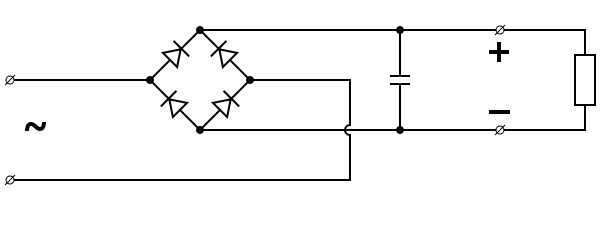
Something like a half-bridge or full-bridge rectifier circuit should do the trick!

As for power supply from 10Vac, no issues really! Either you get an off the shelf AC to DC converter or what i mentioned above might do the job…

Ok. After some googling, a full bridge rectifier seems to be what’s needed to power the core. It’ll give me 10VDC. I can then put a 5V regulator after it to get a nice supply to the core.

I could then re-use that strategy to get 5VDC from point 2. I suppose that would connect to a digital pin then.
Sounds straight forward.

Does rectifying diodes, a 5V regulator, and a smoothing capacitor sound like all I need for each rectifier circuit?
That would then produce a nice clean safe signal and power supply for the spark core?

Yes that’s the usual way we go about doing this :slight_smile:

I’m all over the firmware coding and web app building. I was all over digital circuits and FPGAs in school. Analog circuits were my nemesis though. :smile:

Thanks for the info!

Does this do the trick? Seems like the same solution in a single package. Price is right too.
https://www.futurlec.com/Diodes/2W04Mpr.shtml

Edit: Oh. How do I determine what size capacitor I need?

That’s an overkill for your project but yeah the specs are good for you to even use to convert the typical 110/230V to DC. nice one!

Take a look at this:

Recommended to go through the Vin pin so that it goes through the 5V–>3.3V regulator :smile:

That reminds me of bwired.nl's door cam.

Wow. That took it really far. I’m an analytics nut and even I wasn’t thinking BI for my doorbell!

I’m having doubts on diode and capacitor selection.

All the rectifier diodes I see have a forward voltage rating of 1.1V. Am I right in understanding that’s the voltage it will allow through it? Which means I need a 10V one since my input is 10V.
ex. All the ones listed here on digikey.

For capacitors, I have no idea how to make this selection.
I dug this up
Smoothing capacitor for 10% ripple, C = ( 5 × Io) /(Vs × f )
C = smoothing capacitance in farads (F)
Io = output current from the supply in amps (A)
Vs = supply voltage in volts (V), this is the peak value of the unsmoothed DC
f = frequency of the AC supply in hertz (Hz)

I think to power a spark core off a 10VAC the values are:
Vs = 10
f = 60 (North america)
Io = ??

Is the current value here the current draw of the spark core?

Forward voltage refers to the voltage drop you can expect to see across the device. In this case you’ll go from ~10VAC to ~8.9V DC - not an issue in your case since you’ll be dropping it to 3.3V anyway.

Oh yeah,

We need to see the following:

Vrrm - This is the Max AC Voltage that the bridge rectifier can take

I-forward - This is the Max average current you can get out of the bridge rectifier.

Like what @erjm mentioned, the forward voltage is the voltage drop across the diode so you won’t get exactly 10Vdc our of the supply you will be tapping on.

Got it. Thanks! So the 1N4001 is just fine for this. http://www.fairchildsemi.com/ds/1N/1N4001.pdf

I(f) = 1A
VRRM = 50

Part selected!

That just leaves figuring out the smoothing capacitor value. Is the formula above correct? Do I just need to plug in the Core’s max current draw?

Better to factor in the max draw current but anything about 400mA would be decent.

Wifi transmission takes like 300mA thereabout.

Why not get a bridge rectifier component? :smiley:

@timb I saw your post in another thread where you are also doing AC to DC.

Wanna give @kareem613 some inputs?

Let me check the ripple current tonight when I get home

Sure! I’m doing a thermostat, which generally has a 24VAC input. I’m taking it through a 400V 1.5A Glass Passivated Single Phase Bridge Rectifier (http://www.vishay.com/docs/88769/woo5g.pdf). 400V may seem like overkill, but it’s actually the current carrying ability that determine the size of a diode; this guy fits neatly on a normal PCB. (You can buy these at a Radio Shack: W04G.)

Next, get the biggest capacitor you can fit in the space you have, I’d recommend at least a 1000uF electrolytic, don’t hesitate to stack them. Drop that sucker on the output of the rectifier: This acts as a “storage tank” to help convert your pulsating DC waveform into something that actually looks like DC, I.e., Flat.

You’ll still have ripple at this point, but we’ll take care of that! I’d recommend using a low-noise low-dropout linear regulator to get the voltage down to power your Core or whatever. Be sure to use filtering capacitors on the inputs and outputs.

Check TI.com for good regulators, you can get them in TO-220 packages still, so no need for surface mounting. They give free samples orderable through the website as well. LT also has good linear regulators, but it’s a pita to get samples from them.

I’ll put together some schematics showing how you should hook everything together in the morning if you want (including capacitor values and part number recommendations).

We’ll get you powered up. :smile:

I'm not concerned about overkill. We're talking about a doorbell that sends push notifications over the internet. This whole thing is overkill!

So I'd like to build this around that component. I can picture the schematic with a smoothing capacitor across the DC output and a regulator after that. Do I need more than that?

P.S. Is there a thread about your thermostat project? Now that I'm logging room temp and humidity data to my cloud service, I want to start tracking HVAC usage. Same rectifier solution will do it.

I'll totally take you up on this offer. I'm browsing around mouser.com. Looks like they'll have everything.

Okay, cool! Gimme a few minutes. :smile:

Okay, so here’s what I’d go with:

Here’s a simulated output from the circuit:

You can see the regulator input (green) still has quite a ripple on it (71uV Peak to Peak) and the output (blue) is essentially ripple free (the simulator isn’t quite right, there will still be some ripple). I’ve got a 10uF capacitor on the input of the regulator, which is optional, but I’d still add it; as it helps reduce the input ripple.

Just to show you how much the regulator helps, here’s what you’re looking at without the regulator and just a 1000uF capacitor:


Okay, so back to the circuit! After looking through various regulators, I’d recommend the LM1086-50 from TI. You can also get a free sample direct from TI; just sign up for a free account. (Go here and find LM1086IT-5.0/NOPB then click the Free Sample button.)

On the output of the regulator, put 0.1uF Ceramic, 10uF Tantalum and 47uF Electrolytic capacitors in parallel on the output. (The Tantalum and Electrolytic caps are polarized, so pay attention to how you put them in!)

On the input of the regulator, put a 10uF Tantalum.

Directly on the output of the rectifier (shown as four diodes on the schematic) put between one and three 1000uF electrolytic capacitors. (You can use a higher value, such as 3700uF if you’ve got them handy.)

The capacitors on the input side of the regulator should be at least 25V, the output side should be 10V minimum.

Oh, be sure to slap a decent TO-220 heat sink on the regulator as well. (You can get these at Radio Shack if needed.)

That’s pretty much it! Let me know if this makes sense or if you have questions! :smiley:

1 Like

This is amazing information! I wouldn’t have thought of the extra capacitors for more smoothing. I understand the circuit pretty well.

Off to ordering parts next.Thanks for this. I’ll post progress.

I’m guessing this is the same principle behind an adapter from 110VAC. Does the circuit stay as simple? I ask because I’d love to build my air quality monitor into a light switch box and power it directly off mains power. It would give me a nice simple install for each room. Up until now I was thinking of just ripping an adapter apart.

By the way, make sure that the 10uF on the regulator’s output is a Tantalum capacitor; that regulator needs a specific ESR and calls for Tantalum. The 0.1uF Ceramic and 47uF Electrolytic aren’t required, but they will help keep noise out of the system. (Different size capacitors respond to different frequencies, just like antennas. Those are two common sizes of bypass capacitors, so between all three you should be set!)

As for using that on line voltage, unfortunately, no. 120VAC is far too high for a linear regulator. This is why old school AC Adapters were so big and heavy, they had to include a transformer to bring the voltage down. Modern adapters are the product of very fast and robust power transistors. Though, that’s not to say that they don’t still use transformers. Most higher quality adapters will use a synchronous isolated flyback transformer design for the output voltage regulation. (Essentially you convert the incoming AC into High-Voltage DC with a rectifier, run it through a MOSFET to reduce the voltage then run the chopped DC through a tiny flyback transformer (which converts it what’s essentially low-voltage AC) before finally putting it into a backwards rectifier (which basically means when the transformer is being powered the diodes block). It’s really cool technology!

Here’s a reference design for a 1"x1" 5V/2.1A adapter: http://www.ti.com/tool/pmp8286

Here’s what’s inside of an Apple Charging Cube: http://www.righto.com/2012/05/apple-iphone-charger-teardown-quality.html

Anyway, what I would do if I were you is just get a small cube charger like that (Samsung has one that retails for about $10) and solder AC wires directly to it, then cover the exposed prongs with a couple of layers of heat shrink tubing. This way all the hazardous stuff is safely enclosed. I think that would be safer than taking apart an adapter. (Seriously, be careful though! Live AC is not a joke!)

1 Like