I always see pictures of projects on breadboards, but rarely see pictures of things in protoboard (or stripboard, veroboard, etc.). Even when I do see projects on protoboard, I don’t often see the nitty-gritty wiring and soldering.
I’ll be honest, I haven’t been taught how to solder. I think I’m decent, but I could be doing it all wrong! How do the pros do it (@bdub, @bko, @peekay123)? Show me (and all the other newbies here) how it’s really done. Teach us by example. Impart your wisdom. Share tips and tricks. Or just post pictures of your work. What have other forum members done? I want to see it all, so we can learn from each other.
I’ll share a couple of my more recent projects.
RFID Reader
The design here was meant to go in a wand or “gun” to scan tags of festival attendees.
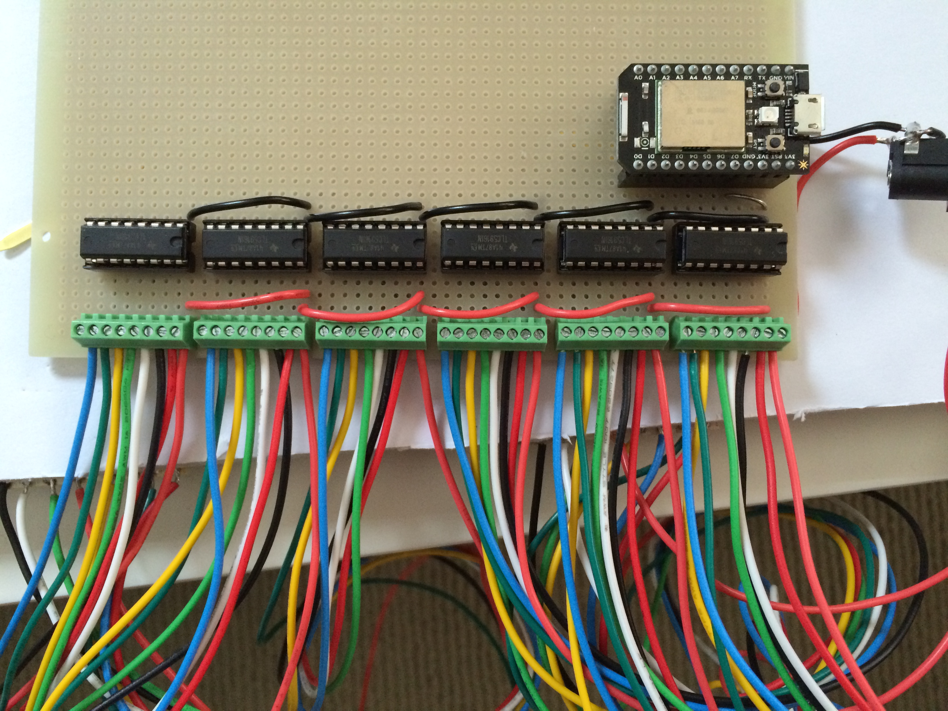
Top with the headers for a Spark Core (or Photon) on the left, and headers for the RFID reader on the right.
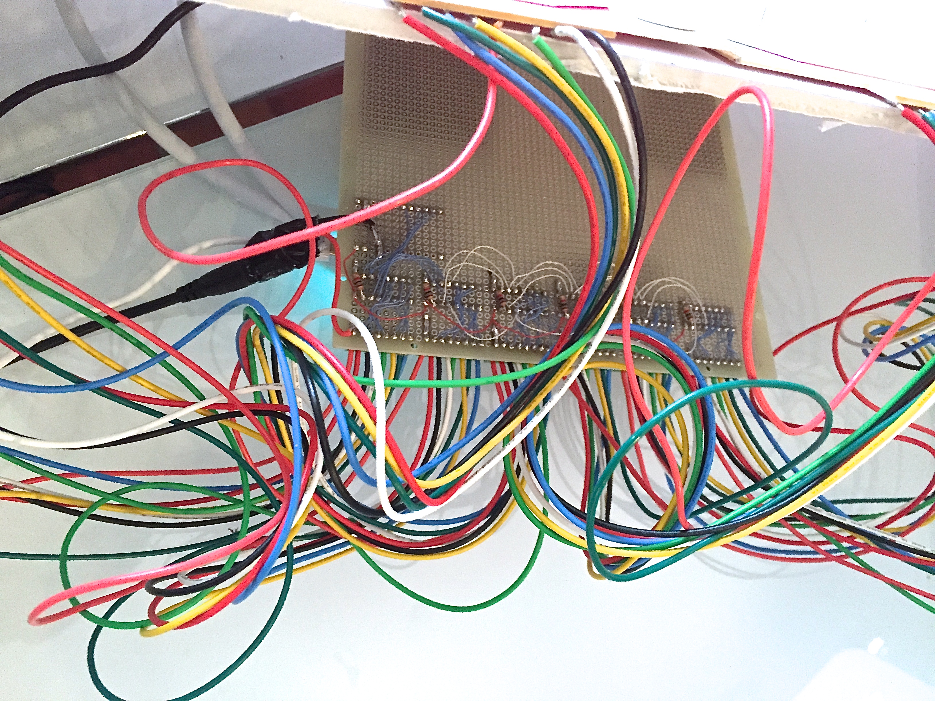
Bottom
__3D Printer Monitor v1__*
Top. Socket for Nokia 5110 LCD on left. Socket for Spark Core in lower right. Terminals are for hooking up external thermistors. A bit of a rat's nest. It works, but just barely. Nothing is connected to the top headers since the pins are mirrored on the other side of the LCD.
The bottom of the nest. The big glob in the middle is common ground. The glob in the top right is common Vcc.
* I found another LCD with buttons and LEDs that I may use for a v2.
I hadn’t yet transitioned this from its original Teensy++ to the Core (or Bluz), but it’s on my ToDo list
This is a Bluetooth DMX controller with a BTM222 module sitting on a daughter board to convert the 1mm ptich to 2.54mm.
And this is my modded (Bluetooth enabled) USB HID mouse that uses my PS2Communication library to receive PS/2 signals of the original mouse and pass them on via USB (with the possibility to manipulate the mouse behaviour via Bluetooth and even send keystrokes and mouse macros ).
i don’t think its possible to make a tidy looking circuit on perfboard where the whole point is to use solder blobs to join stuff up. i personally prefer stripboard, it also tends to need fewer jumper wires.
Speaking of training - All we were ever trained on is a 2-hour look at the standard way of soldering + a bunch of damaged through-hole resistors + stripboard for your practice. That pretty much concluded how i learnt soldering and all the rest is history!
Actually the point was, that I had wanted to remote control (join up with Outlook, online telephone registers, …) some propriatory telephone system in my company.
The only interface that wouldn’t cost several thousand of Euros was/is its USB mouse and keyboard interface.
So I came up with the idea to have a USB HID device, that can receive data via Bluetooth from any application an pass it on to the telephone board via key strokes and mouse actions.
But since our IT doesn’t like it when you hack their equipment, I hid it away into a mouse case, but then decided, the mouse should not only be a case but should also function as if it was a really boring standard mouse, so I added the PS/2-USB HID translation just to keep the illusion alive (and it was fun ;-))
If you are fortunate enough to have NICE tined and plated through-hole vectorboards like the ones you show in the first post Garrett, you too can prototype like a pro!! Those are nice boards Most of your joints look great! Some look a bit cold, and that can be due to use of lead-free solder, are you using that? I’ve found that with a soldering iron lead-free just ends up looking like crap and the joints often don’t bond well so I stick with leaded. The leader the better!
Now if you look at ScruffR’s radio shack phenolic single-sided non-plated through nastyboard, that’s what most people I know use and your stuff ends up looking pretty sketchy. But hey, it works right! Until it doesn’t. Those boards tend to work better if you use some scotchbrite scouring pads or steel wool on the copper pads before you start soldering. Definitely use a leaded fluxy solder. Also, with larger wires, join the wire to multiple pads to spread the mechanical stresses out over several points. Those pads rip off super easy.
Some crazy people I know like to use protoboards with no copper at all. This requires you to secure components with solder blobs and glue. I honestly don’t understand why you would use this type of board. Maybe someone can explain this to me
Here’s some of that nasty radio shack protoboard used to make a jtag programmer for the Spark Core (gallery of a few pics):
I could dig out countless ugly things on protoboard… but I think that answers your question. You can make things way nicer, but really they mostly end up looking like spaghetti.
For the record, typically I try to make my stuff look nice I figure if I color code things, and wire it up LESS like spaghetti, it will be easier to debug… and trust me, you usually are going to be debugging… I don’t care how good you plan ahead.
I'm a big fan of the microtivity merchant on Amazon. That's where I've picked up most of my boards, LEDs (and resistors packaged with the LEDs). They have a great selection of the basic components in good quantities. The prices may not beat stuff you can find elsewhere, but the prime shipping speed and cost are really tough to beat!
Is there a good or recommended way to solder jumper wires to headers? I've just been putting them in adjacent holes and either creating a solder "bridge" or bending the bare wire of the jumpers over ~90° and soldering them directly to the headers.
It depends on how much current is flowing through the connection, but typically solder itself is a pretty decent conductor so you can't go wrong in either case. I like to bridge them as well, which also makes it easier to desolder if you have to. If you bend the wire over, you will have a lower resistance connection (aka better for higher current flow), but it can create a little snag if you need to desolder it. I don't think there's necessarily a right answer here... just your answer for your application
The longer straight parts have wires embedded in them.
When you run the occasional 600-800A through it, your ‘regular’ wires tend not to be sufficient any more That’s when you end up with something like this:
Results were so worth it though
More pics of the built process can be found here, if anyone’s interested. (the albums with “tesla” in it.)


 ).
).
 watching these


 That’s when you end up with something like this:
