I keep having an issue, and it’s clearly me. But I keep melting breadboards. I just realized why, today, as my board next to me started smoking.
I’m going from a 12V battery to a toggle switch to a 12v to 5v converter. From there I go to a terminal block. Half the terminal block is 12V for some downstream things off a relay, and the other half is 5V.
From the 5V half I jumper to + and - lanes of the breadboard. Then I jump from + to VIN and - to GND for the electron.
This is great. I can flip the switch, and power on my particle, power my LCD, etc.
But I flash over USB. So if I’m working remotely, I can be plugged in via USB, switch on the battery off. I can still flash and read serial output.
But I keep melting breadboards if I do this for more than a few hours. So how I can keep plugged in via USB, and not worry about burning down my house while I’m working remotely?
You probably have some kind of short or low resistance connection between one of the positive power rails and ground or some component expected to dissipate a lot of power with too little cooling.
Usually the place where the melting happens - or better before that happens - where things get warm is the location of the error.
Showing schematics and hi-res photos of your setup (and a molten breadboard) may help see potential issues.
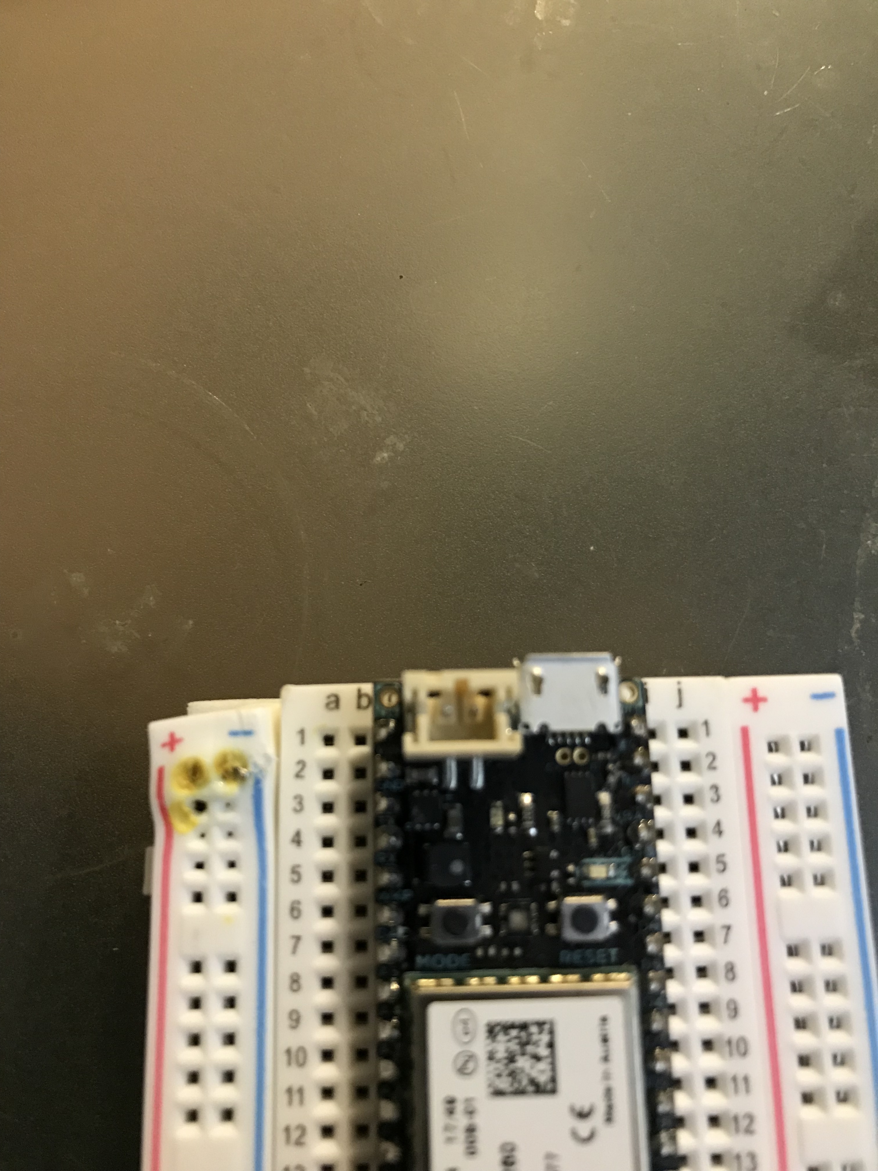
No other problems anywhere else. Here is full breadboard, and it’s earlier caught sibling. The right one I used small cut wire to jumper. I switched to longer jumper wires thinking that might help.
Your setup is obviously drawing too much current for the breadboard rating, but without a schematic it’s hard to tell what kind of current draw to expect.
As a temporary measure you may want to consider multiple feeding points as it seems that on single wire jumper contact (with its contact resistance) will dissipate a lot of power, splitting that over multiple points may help that.
Usually longer jumper wires would rather add to the problem, what you want to use instead are thicker wires and more contact area to reduce the contact resistance.
But as long you haven’t actually figured where the current draw comes from and why this happens I would advise against using that setup as is again.
When powered by USB, VIN is a power output on the Electron. When powered by a laptop it might be 500 mA at 5V, but it could theoretically supply up to 2A at 5V.
I presume your switch is on the 12V side, but what does your power supply circuit do when supplying 5V to the output of your regulator with no power input? That’s what’s happening when powering by USB. You may want to add a Schottky diode to prevent current from flowing from VIN into the output of your 5V regulator.
And while you should find the source of your problem, the other alternative is to use USB without power. I built these little boards that allow USB data but disconnect the power line. It's the opposite of a data block cable - it allows data (and GND) but disconnects the USB power line so you can use your external power supply safely while still allowing USB serial to work.