MCP32F521 Library Port to Particle

Hello, @peekay123

I’m creating a new thread to talk about porting over a library. The library works on an Arduino Mirco without issue. When I try porting over to an Argon/Boron I get a Checksum mismatch error.

Serial Output

checksumTotal:: 346
aucWriteDataBuf[7]:: 90
aucWriteDataBuf[0]:: 165
aucWriteDataBuf[1]:: 8
aucWriteDataBuf[2]:: 65
aucWriteDataBuf[3]:: 0
aucWriteDataBuf[4]:: 2
aucWriteDataBuf[5]:: 78
aucWriteDataBuf[6]:: 28
Error returned! 5

Write now I; going through line by line trying to find out what data is being sent that is incorrect based on the datasheet; which is linked in the README.md of the git repository.

Error Retuned! 5 = ERROR_CHECKSUM_MISMATCH = 5 line 164 on upbeatlabs_MCP39F521.h

You can find the entire code base included the “library” files in this repository I just pushed to a public git.

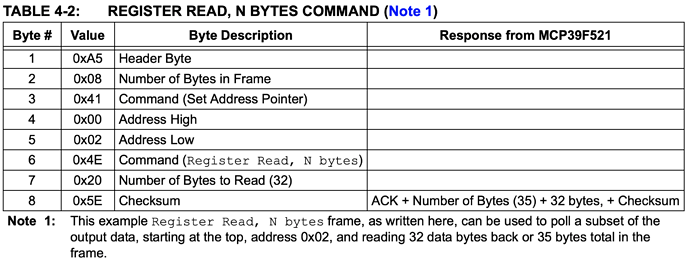
Here is a Logic analyzer screenshot for the same code running above. This Section is Setup to [0xE9] + Ack and appears to be missing the ask on the last bit.

I’ve used many STM32 M4 processors, so I have familiarity there, I’m not completely familiar with the difference between Ardunio “Atmel” and the like. If you have any pointers or recommendations on how I can port this library better or where I should be looking to get it working please let me know. I’d appreciate the education and knowledge.

I have not had a look at the library yet, but ...

One of the differences that might be the contributing here is the endianness. If you read bytes into a structure containing multi-byte integer values you may need to flip the byte order.


Update:
Your checksumTotal is 346 and aucWriteDataBuf[7] is 90 which would fit the bill for 346 % 256 (which is used for calculating the checksum).

In that library there are many places where a checksum is calculated and compared - which function specifically does render that error?

In that library there are checks like this

  int requestDataLength = Wire.available();
  if (requestDataLength==(numBytesToRead + 3)) {

but there is no distinct treatment for the case where that check fails. This could happen due to some timing issue as it is executed immediately after the Wire.requestFrom() call by which time not all data may have been received already.

For my part I'd rather use the Stream features of the Wire object to send and receive multiple bytes than "handcrafting" the transfer like this.

BTW, what device OS version are you targeting? In older versions there was an I2C bug that could cause similar issues.

1 Like

Hello @ScruffR

Thanks for the information, I haven’t thought about endianness, but that could be the issues. Will Explore more now. Yeah, the 346 % 256 = 90 so that is working as expected, meaning the data is being sent incorrectly not that the checksum is not working as expected.

I’m using Particle 1.5.2 OS for this project.
Based on the Nordic Datasheet it also doesn’t have a limit of 32 bytes.

// Arduino cannot read more than 32 bytes on I2C
// Splitting out activeEnergyImport, activeEnergyExport and
// reactiveEnergyImport, reactiveEnergyExport into two calls
// as the total is 32+3 = 35 bytes otherwise.

Do you know if the Particle OS has the same 32 Byte limitation in the HAL layer?

In the .ino script, I’m only using read(data, NULL); [Line 97] funtion that calls registerReadNBytes((uint16_t addressHigh, uint16_t addressLow, uint16_t numBytesToRead, uint8_t *byteArray, uint16_t byteArraySize);) [line 1245]

I’ll let you know what I find. If you see anything else that might be helpful let me know, debugging code is often harder than writing it from scratch but a great skill to foster.

Thanks,
Nicholas

This should answer that question :wink:
https://docs.particle.io/reference/device-os/firmware/argon/#acquirewirebuffer

Thanks, looks like that is a yes, ugg, looks like it only a HAL limitation not a chip limitation.
What do you mean by `Stream" with I2C?

Actually this link should show the opposite. In fact it shows that the device OS does offer a way to go beyond the default 32 byte limit.

The TwoWire class inherits from the Stream class as indicated in the docs

Hence you can use methods provided therein too - e.g. Wire.readBytes()

1 Like

That is a really great thing to know! Yet not clean in the documentation. Thanks.

uint8_t aucReadDataBuf[35];
  //int i;
  int retval = 0;

  if (output) {

    retval = registerReadNBytes(0x00, 0x02, 32, aucReadDataBuf, 35);
  
    if (retval != 0) {
      return retval;
    } else {
    
      /* System status */
      output->systemStatus = ((aucReadDataBuf[3] << 8) | aucReadDataBuf[2]);
      output->systemVersion = ((aucReadDataBuf[5] << 8) | aucReadDataBuf[4]);
      output->voltageRMS = ((aucReadDataBuf[7] << 8) | aucReadDataBuf[6]);
      output->lineFrequency = ((aucReadDataBuf[9] << 8) | aucReadDataBuf[8]);
      output->analogInputVoltage = ((aucReadDataBuf[11] << 8) | aucReadDataBuf[10]);
      output->powerFactor = (((signed char)aucReadDataBuf[13] << 8) +
                             (unsigned char)aucReadDataBuf[12]);
    
      output->currentRMS =  ((uint32_t)(aucReadDataBuf[15]) << 24 |
                             (uint32_t)(aucReadDataBuf[16]) << 16 |
                             (uint32_t)(aucReadDataBuf[17]) << 8 |
                             aucReadDataBuf[14]);
      output->activePower =  ((uint32_t)(aucReadDataBuf[19]) << 24 |
                              (uint32_t)(aucReadDataBuf[20]) << 16 |
                              (uint32_t)(aucReadDataBuf[21]) << 8 |
                              aucReadDataBuf[18]);
      output->reactivePower =  ((uint32_t)(aucReadDataBuf[23]) << 24 |
                                (uint32_t)(aucReadDataBuf[24]) << 16 |
                                (uint32_t)(aucReadDataBuf[25]) << 8 |
                                aucReadDataBuf[22]);
      output->apparentPower =  ((uint32_t)(aucReadDataBuf[27]) << 24 |
                                (uint32_t)(aucReadDataBuf[28]) << 16 |
                                (uint32_t)(aucReadDataBuf[29]) << 8 |
                                aucReadDataBuf[26]);
    }

Do you know if the array order needs to be flipped here to deal with big Indian?

I must admit that I have not consulted the datasheet for that sensor nor looked deeply into the library and I’m not really planning on doing so, but these bit operations seem odd to me.
You are are constructing a uint32_t from the bytes in your array in the order 1, 2, 3, 0.
I’d understand 0, 1, 2, 3 or 3, 2, 1, 0 but not what I’m seeing there.

1 Like

I’m really struggling with this now, for some reason I can’t wrap my head around the big-endian and little-endian difference for I2C. As you can see I tried swapping the data order and sending it using a LittleWne

This is the only code I’m running, I’m just trying to figure out the crazy ness on the I2C bus. Not the code works perfectly on an Arduino.

I’ve read the datasheet a few times now, focusing mainly on Table4.2 teh read - N-bytes command.

void setup() {    
  WiFi.off();            
  Serial.begin(115200);  //turn on serial communication  
  Wire.setSpeed(CLOCK_SPEED_100KHZ); // Set Speed to 400kHz for production 100kHz for debugging 
  Wire.begin(); 
 }

void loop() {
  uint8_t numBytesToRead = 28;
  uint8_t ReadDataBuf[8];
  uint8_t LittlEendianData[8];
  uint8_t byteArray[35];
  uint32_t checksumTotal = 0;
  int i2c_addr = 0x74;
  int i;

  ReadDataBuf[0] = 0xA5; // Header
  ReadDataBuf[1] = 0x08; // Num bytes
  ReadDataBuf[2] = 0x41; // Command - set address pointer
  ReadDataBuf[3] = 0x00;
  ReadDataBuf[4] = 0x02;
  ReadDataBuf[5] = 0x4E; // Command - read register, N bytes
  ReadDataBuf[6] = 0x20;
  ReadDataBuf[7] = 0; // Checksum 0x05E - computed below
  for(i = 0; i < 7; i++) {
    checksumTotal += ReadDataBuf[i];
  }
  ReadDataBuf[7] = checksumTotal % 256; // 0x5E = 94 
  // Flip the data for little endian 
  for(i = 0; i < 8; i++){
    LittlEendianData[i] = ReadDataBuf[8 - i];
  }
  Wire.beginTransmission(i2c_addr);
  for(i= 0; i < 8; i++) {
    Wire.write(ReadDataBuf[i]);
  }
  Wire.endTransmission();
  // delay(100);
  //
  // Read the specified length of data
  //
  Wire.requestFrom(i2c_addr, (uint8_t)(numBytesToRead + 3)); 
  int requestDataLength = Wire.available();
  if (requestDataLength==(numBytesToRead + 3)) {
    //Wire.readBytes((char*)byteArray, requestDataLength); //Wire.readBytes((byte*) byteArray[I], requestDataLength);
     for (i = 0; i < (numBytesToRead + 3) ; i++) {
       byteArray[i] = Wire.read();
      }
   }
  // delay(1000);
}

When in run the code with everything after the Read the specified length of data comment I get a clean logic analyzer capture.

As you can see, A5, 08, 41, 00, 02, 4E, 20, 5E all form the read command.

Yet when I add the Wire.requestFrom(i2c_addr, (uint8_t)numberBytesToRead + 3)); I get strange SCLK strechingwhich makes no sense. If I remove the first delay(100);


Column one shows just the Wire.write(); command (ReadDataBuf), Column two shows when I add the Wire.read(); command code, Column Three show what it looks like Working on an Arduino.

I’m not sure why the CLK has any early trigger and irregularity, it’s like it’s being stretched and messed with yet nowhere in teh above code is that support to happen.

I’m now on day 3 and I feel like I’m going backward, so any help would be appreciated.

@ScruffR I also tried Wire.readBytes(((char*)byteArray, requestDataLength)); but I’m not sure that really helped as the data was more chaotic.

Thanks again for the help :slight_smile: !

Since your table shows an expected response length of 35 bytes it may be required to use Wire.acquireWireBuffer() in setup()

With a 32 byte buffer and a 35 byte response the master has to indicated to the slave that the buffer is full and no more data can be transmitted till more room is made in the buffer (e.g. by reading the already received data).

I get this error trying to add this function class "TwoWire" has no member "acquireWireBuffer"
https://docs.particle.io/reference/device-os/firmware/argon/#acquirewirebuffer

The documentation looks like I'm creating an entity new function that then sets the size in teh HAL layer. Is that correct?

My bad, it’s not Wire.acquireWireBuffer() but should be done as shown in the docs :blush:

With that you are “overloading” the default implementation of the function that is used to acquire the buffer.

I don’t understand what the documentation is asking for,

constexpr size_t I2C_BUFFER_SIZE = 512;

HAL_I2C_Config acquireWireBuffer() {
    HAL_I2C_Config config = {
        .size = sizeof(HAL_I2C_Config),
        .version = HAL_I2C_CONFIG_VERSION_1,
        .rx_buffer = new (std::nothrow) uint8_t[I2C_BUFFER_SIZE],
        .rx_buffer_size = I2C_BUFFER_SIZE,
        .tx_buffer = new (std::nothrow) uint8_t[I2C_BUFFER_SIZE],
        .tx_buffer_size = I2C_BUFFER_SIZE
    };
    return config;
}

Can you explain what is going on here?

I think I figured out how to use it.
Wire.requestFrom(WireTransmission(I2C_ADDRESS).quantity(I2C_BUFFER_SIZE).timeout(100ms));

I’m still having this problem of the ACK missing on the read command.

constexpr size_t I2C_BUFFER_SIZE = 32;
constexpr uint8_t I2C_ADDRESS = 0x74;
void setup() {
    WiFi.off();
    Wire.begin();
}

void loop() {
  uint8_t numBytesToRead = 28;
  uint8_t ReadDataBuf[8];
  uint8_t byteArray[35];
  uint32_t checksumTotal = 0;
  int i;

  ReadDataBuf[0] = 0xA5; // Header
  ReadDataBuf[1] = 0x08; // Num bytes
  ReadDataBuf[2] = 0x41; // Command - set address pointer
  ReadDataBuf[3] = 0x00;
  ReadDataBuf[4] = 0x02;
  ReadDataBuf[5] = 0x4E; // Command - read register, N bytes
  ReadDataBuf[6] = 0x20;
  ReadDataBuf[7] = 0; // Checksum 0x05E - computed below
  for(i = 0; i < 7; i++) {
    checksumTotal += ReadDataBuf[i];
  }
  ReadDataBuf[7] = checksumTotal % 256; // 0x5E = 94 
  Wire.beginTransmission(WireTransmission(I2C_ADDRESS).timeout(100ms));
  for(i= 0; i < 8; i++) {
    Wire.write(ReadDataBuf[i]);
  }
  Wire.endTransmission();
  // delay(100);
  Wire.requestFrom(WireTransmission(I2C_ADDRESS).quantity(I2C_BUFFER_SIZE).timeout(100ms));
  delay(2000);
}


This is the Setup Read [0xE9] command failing, shouldn’t Particle’s I2C library Wire.Request handle the clock and the ACKs?

Also, why do you think the data get’s corrupted if I uncomment the //delay(100); right after the end transmission? It’s a strange behavior that in theory shouldn’t effect the data at all, because at that point the I2C bus should be let go and pulled up to VCC yet that doesn’t seem to be happening. I’m I not understanding that code correctly?

This is probably something for @rickkas7 or a support ticket.

I’m able to get data now! It took some tweaking and trail and error yet the issues I’m still getting is missing ACK and NAK on some reads. It’s not constant so I think it might be a wire issues now not a software issues. I’m hooking up to an oscilloscope next to try and see if I’m pulling too much current from the particle 3V3 bus, unlikely but worth checking.

Here is the code that is working


The output that I’m reading on the I2C bus.


What i’m reading out on serial monitor.

The read command looks like it’s not sending the right data, so I might have my address incorrect based on the datasheet.

Will keep you update to my progress.

1 Like

Which Microchip device are you using? MCP39F521?

Hello Armor,

Exactly, using the MCP39F521 on this dev board from Microchip. There is an isolator chip between the Argon and the Dev MCP39f521. I have 5 vendors chips I’m evaluating and I’ve only had issues with this one, the others use SPI. I’m running the i2c bus at 100Mhz and have nothing else hooked up, just troubleshooting this interface. I get data but the bus seems to have issues with stability now. I’m not sure what else I could be doing wrong. I set up the Write command just like the datasheet, I’m just noting getting the 0x06 back every time like it should when I start the read command.

Sometimes I get Start bit generation timeout::2 from the Wire.endTranmission(); command which tells me something is wrong with the timing, but I’m not sure how to fix this without accessing the HAL layer.

Still working on a solution, but because I can get data sometimes that is correct; comparing with a multimeter shows the voltage and current are correct; I’m confident this IC will be useable in a product. Just needs more software tweaking to run performance test.

Would you mind sharing what other ICs you are evaluating? I am looking for a ‘all in one’ solution to measuring current and determining whether AC voltage is present. To date have used AC712 Hall Effect sensor for AC current but requires lots of processing of readings, a current sensor transformer with a dedicated IC - works but expensive, voltage sensing with MID400 optocoupler - expensive due to AC current limiting. The MCP39F521 looks interesting (or the SPI equivalent) - I would ideally like something to monitor 20 AC outlets.