Out of the s designs, I’d recommend either the MCP39F521 or the ADS7250 but note that you can only have 4 MCP39f521 on a single I2C bus. A shunt resistor lower resistance and accuracy is often better a hall effect sensors. I started the project with a Hall effect sensor but ran into a few limitations that promoted this research into what method woks best for our application. I will say if cost is not a consideration a good CT (Current transformed) to a accurate ADC like the ADS produced great results. We just can’t package a CT in our design well.
Thanks for sharing that info. I use a CT and a special IC that removes the need for a lot of passives but together they are very costly as you mention.
The limit on I2C bus addresses and also that it would require 1 MCP39F521 for each power outlet makes it too expensive for that sort of use for me. What have you assessed the cost of the passive components to be? As an overall power usage monitor it is interesting though as one can just read the output and not have to do stuff on the Particle device. Did you get the I2C working with Gen3?
Looking at the Microchip site I see they have 2 multichannel ADCs the MCP3914 and MCP3913 that appear to have reference designs for current monitoring using shunt resistors for 6 way socket outlets.
Had you considered these?
Not sure about the rather complicated power supply and ground plane requirements as well as the control via SPI which would require an on board co-processor MCU to manage the readings. Generally have found I2C more practical than SPI.
I still haven’t gotten a reliable reading with Gen3, but have gotten it working on an ESP32, STM32, and Atmel 32u. I’m not sure why the clock is starting before the start bit is called with particle no other device has this problem. At this point, I’m digging into the HAL layer.
I have looked at the MCP3914 but I only require one monitor per device and care a lot about the cost. Don’t overthink the GND plans it’s easy to understand, you just have an AGND and DGND and that is common in analog sensing designs.
I find SPI to be easier, I2C has way more overhead and is harder to debug because you are relying on the IC and the library to do a lot of the work.
Hope you find a good solution, what is your application for?
@Nicholas, I have experienced the SPI CLK problem like yours on another project. In my case, I believe it was caused by the “on-the-fly” changing of the bit order from MSBFIRST to LSBFIRST. I also believe it may be caused by the use of begin/endTransaction() functions which also set the SPI hardware configuration. However, I need to do more testing to confirm.
@Nicholas, can you post your code or a link to the MCP3914 SPI library you are using? The glitch on the CLK pin can be remediated with proper timing of the CS line going active.
Hello @peekay123 I’m having issues with I2C, not the SPI communication, on MCP39F521, not the MCP3914.
The issue is really strange but consistent, I’m getting a particle debugger today to drive deeper. I believe the issue is that the I2C clock starts early messes up the NAK and ACK acknowledgments. It’s strange because the code works perfectly on many other devices but Particle I2C implementation seems to have trouble holding the clock high, and I have no clue why. Let the real mystery begging begin.

You can see that the clock is low and start with the wrong frequency before any data is transmitted.
Git Repo where I’m debugging this issue.
I had two firmware developers I use to work with look at the code and we are all perplexed, I’m spending tonight writing it all from scratch in a slightly different manner.
@ScruffR, @peekay123, @armor how would you think to send the Read Command in a different way? I’ve been using Wire.read(); I’ve tried Wire.readBytes(); but have a question about any typecasting.
Wire.readBytes((uint8_t*)&i2c_received, numBytesToRead);` // ERROR from partcile IDE
Wire.readBytes((char*)&i2c_received, numBytesToRead); // The documentation ask for a char
What is the difference and would I need to convert back to uint8_t to use that values?
Here is my I2C Code that is setting up the write and then requesting the data.
int readMCP39f521(int addressHigh, int addressLow, int numBytesToRead, uint8_t *byteArray, int byteArraySize)
{
  uint8_t _i2c_device_address = 0x74;
  uint8_t checksum = 0;
  //uint32_t rawData = 0;
  uint8_t writeData[8]; //= {0xA5, 0x08, 0x04, addressHigh, addressLow, 0x4E, numBytesToRead, 0}
  writeData[0] = 0xA5;
  writeData[1] = 0x08;
  writeData[2] = 0x04;
  writeData[3] = addressHigh;
  writeData[4] = addressLow;
  writeData[5] = 0x4E;
  writeData[6] = numBytesToRead;
  writeData[7] = 0;

  for(int i =0; i<7; i++){
    checksum += writeData[i];
  }
  writeData[7] = checksum % 256;

  Wire.beginTransmission(_i2c_device_address);
  for(int i=0; i<8; i++) {
    int bytesWritten = Wire.write(writeData[i]);
  }
  if(Wire.endTransmission()) {
    return 2;  // Transmission error
  }
  Serial.print("\n");
  if (Wire.requestFrom(_i2c_device_address, (uint8_t)(numBytesToRead + 3))) {
    int bitsRead = Wire.readBytes((char*)byteArray, numBytesToRead);
    Serial.print(bitsRead); Serial.println(" ");
    //Serial.print(rawData); Serial.print(" ");
    if(bitsRead == 0){
      return 3;
    }
  } else {
    // Can't read temperature
    return 5;
  }
  Serial.print("\n");
  return 0;
}
Thanks for the help.
At the fundamental memory view there is no difference at all. Both - char and uint8_t - are single byte datatypes and there is little that can be different between 0x12 stored in a char and 0x12 stored in a uint8_t (or even int8_t for that matter).
Furthermore, typecasting doesn't change the data but merely how the data in the given place is treated.
Since the Wire.readBytes() is expecting a char* you just tell it (via the typecast): "Don't worry, what you are getting is what you need - I, the programmer, know what I'm doing ![]() ".
".
However, since we don't see the definition of your i2c_received I'm not sure whether your ampersand (&) in Wire.readBytes((char*)&i2c_received, numBytesToRead) is correct.
@ScruffR I have a data structure I’m passing into my read MCP32f521 data function. I’m not using the & in my code, while it is used in other functions that do work to get temperature over I2C. This is my current call and I’m no storing the return data from the function to check for errors there.
int bitsRead = Wire.readBytes((char*)byteArray[i], numBytesToRead);
Thanks for cleaning up my confusion between uint8_t and char data types here, I figured as much but didn’t know if the stream.readBytes() function was doing something strange that it only accepts the char data type.
I’m finding that I have the Wire.Write() working correcting but getting a missing ACK after I call `Wire.readBytes(). It appears that the request is working correctly too, so I’m not sure what the best method to debug this further is.

I’ve added error handling by validating the data coming back from the I2C function calls to make sure they are working correctly and everything checks out until this point. What else could I try to check that the timing and data are getting to the MCP39f521 correctly?
I’ve changed how I set up the Wire.readBytes() function by checking all the Wire.X() functions return expected values. See this code below to see how I’m checking each retune value from the Wire.X() functions.
  delay(10); // This allows the requestDataLength to return a value, without it requestDataLength = 0;
  Wire.requestFrom(_i2c_device_address, (uint8_t)(numBytesToRead + 3));
  int requestDataLength = Wire.available();
  Serial.print("requestDataLength: ");Serial.print(requestDataLength); Serial.print(" ");
  Serial.print("numBytesToRead: ");Serial.print(numBytesToRead); Serial.print("\n");
  if (requestDataLength == (numBytesToRead + 3))
  {
    for(int i=0; i < numBytesToRead + 3 ; i++ )
    {
      int bitsRead = Wire.readBytes((char*)byteArray[i], numBytesToRead);
      // Serial.print(rawData[i], HEX); Serial.println(" ");
      if(bitsRead == 0){
        return 3;
      }
    }
  } else {
    return 5;
  }
  return 0;
Also, byteArray is a structure that the function points two and I’m getting a warring "message": "cast to pointer from integer of different size [-Wint-to-pointer-cast]" when I try to add data with Wire.readBytes((Char*)byteArray, numBytesToRead); I think I can ignore this error because the uint8_t is the same as the char I’m typecasting too but the compiler doesn’t see that has mentioned above.
How come you are calling Wire.readBytes() in a loop?
Wire.readBytes() should already read all the bytes in one go.
As is the code is trying to read (numBytesToRead + 3) * numBytesToRead and would potentially also write data into areas outside byteArray[].
I'd expect this should be all you need to read all the bytes (no for() needed)
int bitsRead = Wire.readBytes((char*)byteArray, numBytesToRead + 3);
(the return value is not the bits but the bytes read)
BTW, you can use Serial.printlnf() instead of code like this
looks better this way
  Serial.printlnf("requestDataLength: %d numBytesToRead: %d"
                 , requestDataLength
                 , numBytesToRead
                 );
I've tried this now a few times and figured out that It doesn't need to be in a loop last night after more research. The loop was there when I was using `rawData[i] = Wire.read()' and storing it that way, between bouncing around with solutions I let that slip.
Thanks for the pro tip on the Serial.printlnf() The lines are purely there to try and find the issue; ideally, there is no serial output anywhere in the code, so once it's stable will all go away.
The update on where I was able to get to last night. Right now, I have the MCP39F521 working on an Esp32, an Atmel32uF, and still, I'm getting i2c chaos with Particle gen3 boards. I've tried an Argon and a Boron and get the same unexpected behavior. Which rules out a defective board.
I have confirmed I can use the I2C bus on Argon with an LM75 temperature sensor. So we know I2C does work for other sensors.
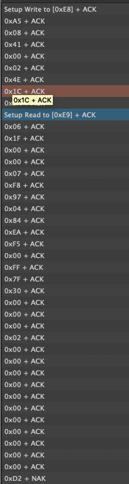
To start, I can step the read command based on the datasheet and send that repeatedly without any I2C bus errors.

Screen Short from MCP39F521 datasheet on I2C read bytes.

Logic analyzer perfect capture of the Write command. Based on the datasheet the MCP32F521 7 bit address is 0x74 where the Wire.beginTransmission(_i2c_device_address); adds the Write bit as 1, and we get a hex value of 0xE8. Everything else is set in code and matches the datasheet.

int readMCP32f521(int addressHigh, int addressLow, int numBytesToRead, uint8_t *byteArray, int byteArraySize)
{
  const uint8_t _i2c_device_address = 0x74;
  uint8_t checksum = 0;
  uint8_t writeData[8]; //= {0xA5, 0x08, 0x41, addressHigh, addressLow, 0x4E, numBytesToRead, 0}

  writeData[0] = 0xA5;
  writeData[1] = 0x08;
  writeData[2] = 0x41;
  writeData[3] = addressHigh;
  writeData[4] = addressLow;
  writeData[5] = 0x4E;
  writeData[6] = 0x20;
  writeData[7] = 0;
  for(int i =0; i<7; i++){
    checksum += writeData[i];
  }
  writeData[7] = checksum % 256;

  Wire.beginTransmission(_i2c_device_address);
  int bytesWritten = 0;
  for(int i=0; i<8; i++) {
    bytesWritten += Wire.write(writeData[i]);
  }
  if(Wire.endTransmission()) {return 2;} // Transmission error
  Serial.printlnf("Bytes Written: %d", bytesWritten);
  // Note there is no read commands here after the write commands, will add in next test.
  return 0;
}
Last night I tried to simplify the function more and find exactly which line of code was creating problems.I removed each line of Wire.XX(); to try and find what was creating this unexplainable issue and two things jumped out at me as major problems.
The first sign of trouble is when I call Wire.requestFrom(_i2c_device_address, numBytesToRead + 3);.Without calling anything after this function to read data, the bus starts behaving erratically.
  if(Wire.endTransmission()) {return 2;} // Transmission error
  Serial.printlnf("Bytes Written: %d", bytesWritten);
  delay(10);
  if (Wire.requestFrom(_i2c_device_address, numBytesToRead + 3)) {
     // letf empty to test just one more Wire funtiona call.
  }
This one line of added code, with our without the if statement takes what appears to be a working I2C Write calls and plays ping pong with the bus! '


I do from consistent predictable data with Write to the bus not being released, missing ACK's and loops of calls that seem out of place. I have no idea why Wire.requestFrom(); is causing these issues when it works perfectly on teh LM75 temperature sensor.
I can run the code on a 32u4 processor and I get perfect behavior.

So the fact this works on other devices leads me to believe it's a particle HAL lawyer issue, or I'm setting up the Read command incorrectly and MCP32F521 is getting confused and sending back gibberish.
The other thing that really worries me is the for a loop in the
for(int i=0; i < 35 ; i++ ){
          Serial.print(byteArray[i], HEX);
      }
it should return every time 35 Bytes no matter what! This is not the cause. What I get into the terminal is varying lengths of data being sent back.
Bytes Written: 8
8623007F8A349EEAF4000000000000000000000555555
bytesRead: 32
MCP_FUNC_RETUNE_VAL:0
Data Avalible

MCP_FUNC_RETUNE_VAL:2
I2C MCP39F521 Error!

Bytes Written: 8
8623007F8A949EEAF4000000000000000000000555555
bytesRead: 32
MCP_FUNC_RETUNE_VAL:0
Data Avalible

MCP_FUNC_RETUNE_VAL:2
I2C MCP39F521 Error!

Bytes Written: 8
8623007000000000000000000000000000555555
bytesRead: 32
MCP_FUNC_RETUNE_VAL:0
Data Avalible

MCP_FUNC_RETUNE_VAL:2
I2C MCP39F521 Error!

Bytes Written: 8
8623007000000000000000000000000000555555
bytesRead: 32
MCP_FUNC_RETUNE_VAL:0
Data Avalible

MCP_FUNC_RETUNE_VAL:2
I2C MCP39F521 Error!

Bytes Written: 8
8623007F8A949E00000000000000000000000555555
bytesRead: 32
MCP_FUNC_RETUNE_VAL:0
Data Avalible

MCP_FUNC_RETUNE_VAL:2
I2C MCP39F521 Error!

Bytes Written: 8
8623007F8A949EEAF4000000000000000000000555555
bytesRead: 32
MCP_FUNC_RETUNE_VAL:0
Data Avalible
This means something is seriously breaking because I believe that if I loop 35 times it should send back 35 bytes of data every time no matter what. So this one really confuses me.
Additional Documentation:
The schematic for the DevKit ADM00686 that has the MCP39f521 and the link to teh dev kits webpage. http://ww1.microchip.com/downloads/en/DeviceDoc/ADM00686%20Rev%201%20Schematics.PDF
https://www.microchip.com/DevelopmentTools/ProductDetails/PartNO/ADM00686
Only 4 wires are used to the Argon, 3v3, GND, SDA, and SCL. They are connected to the I2C header J5. I've confirmed that this works with #v using the 32u4 Feather that is also 3V3 logic.

MCP39f521 Datasheet https://ww1.microchip.com/downloads/en/DeviceDoc/20005442A.pdf
Page 15 is where it takes about using the I2C bus.
Right now I'm looking at the HAL layer trying to figure out why Wire.requestFrom(); is turning what should be a simple request into something so crazy.
Here is the V1 test code I'm working on right now, https://github.com/NicholasJohnson9149/MCP39F521_Test_Code/tree/v1
The only function of interest right now is:
int readMCP32f521(int addressHigh, int addressLow, int numBytesToRead, uint8_t *byteArray, int byteArraySize)
{
  const uint8_t _i2c_device_address = 0x74;
  uint8_t checksum = 0;
  uint8_t writeData[8]; //= {0xA5, 0x08, 0x41, addressHigh, addressLow, 0x4E, numBytesToRead, 0}

  writeData[0] = 0xA5;
  writeData[1] = 0x08;
  writeData[2] = 0x41;
  writeData[3] = addressHigh;
  writeData[4] = addressLow;
  writeData[5] = 0x4E;
  writeData[6] = 0x20;
  writeData[7] = 0;
  for(int i =0; i<7; i++){
    checksum += writeData[i];
  }
  writeData[7] = checksum % 256;

  Wire.beginTransmission(_i2c_device_address);
  int bytesWritten = 0;
  for(int i=0; i<8; i++) {
    bytesWritten += Wire.write(writeData[i]);
  }
  if(Wire.endTransmission()) {return 2;} // Transmission error
  Serial.printlnf("Bytes Written: %d", bytesWritten);
  delay(2);
  if (Wire.requestFrom(_i2c_device_address, 35)) {
      int bytesRead = Wire.readBytes((char*)byteArray, 35);
      for(int i=0; i < 35 ; i++ ){
          Serial.print(byteArray[i], HEX);
      }
       Serial.print("\n");
       Serial.printlnf("bytesRead: %d", bytesRead);
  } else {
    return 5;
  }

  return 0;
}
That’s some elaborate testing you’ve done there.
I think it’s best if @avtolstoy may be taking this from here as this could have something to do with the HW implementation of the I2C comms (although @rickkas7 is also welcome to chime in  )
)
I’ve reached out the particle support, just felt it was easier to link to this than add it to an email. 
Yeah, the hardware setup’s simple, it’ 4 wires to the Argon and I’ve checked it with 3 other dev boards to verify it. I can’t image the hardware being the issue but I wont rule anything out until I know why this is happening.
Thanks again for all the help @ScruffR you are one of the people who makes Particle great!
I recently had a Battery Management chip that communicates via I2C.
It worked just fine on the Photon but when I ran the same code on the Argon it wouldn’t communicate successfully for some reason.
Somebody else that ran into the same issue told me to enable 400khz I2C communication on the Battery Management chip to fix the issue. That did fix the issue for me.
I guess making the battery management chip think the i2c bus would be running at 400Khz allowed it to communicate properly.
Does that mean the Argon’s I2C bus could be running slightly quicker than expected? I have no idea but wanted to throw this out there.
@RWB Thanks for the information, you are correct the 100KHx produces errors. I’m not sure why that is but that is in reality not acceptable for the device OS. Luckily enough the MPC39FXXX can operate at either 100 and 400KHz, not all I2C devices are so lucky.
One issue was that I was using Device OS 1.4.4 which doesn’t support 32-bit I2C reads on Gen 3 devices. I was able to get things working better after updating to Device OS 1.5.2 but have just jumped to 2.0.0.rc.1
This fixed the chaos in the I2C when calling the Wire.readBytes(); function. This cleared up all missing ACK errors on the bus.
What I still have an issue with is reading data, meaning I’m just getting back 0xFF from the MCP32f521. Working now on debugging this issue more. I’ve been told by Microchip that some % of there chipsets that requires shifting over 2 bytes to read the data properly.
Right now I get proper Write setup like before, that perfectly matches what I’m getting on an Arduino or ESP32.
Pictures are from a working Arduino Logic Captures

Write Setup on Arduino

Read Data from MCP on Arduino
Both Read and Write Values from the Arduino
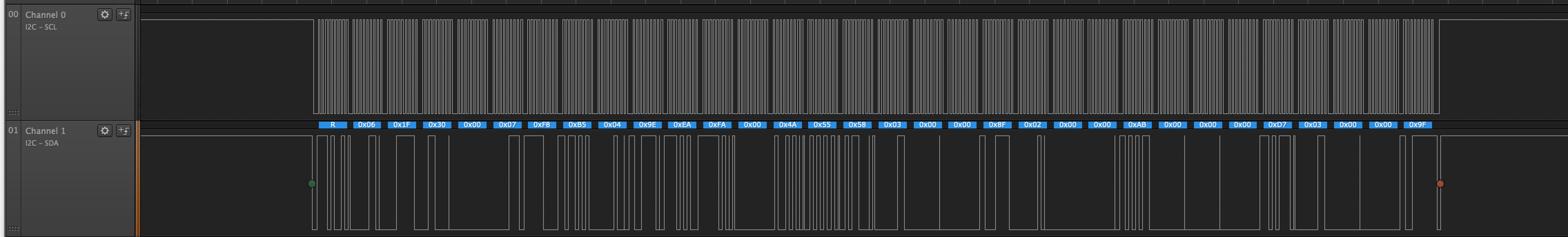
Now looking at the Argon running Device OS 2.0.rc.1 everything starts off looking good.

Argon Write Setup

Argon Not Reading Data, I’m now getting clean data back but it’s just 0xFF, I tried initializing the data to 0x55 to make sure it’s not just reading nothing. It’s getting information from somewhere!
I’m expecting the first response to be 0x06 based on the datasheet and the Arduino code working.
Yet each time I get back 0xC(N+1) or something that is incorrect. It’s like I’m pointing to the wrong location in memory. Any ideas on how to check this?
Based on the Litle Endian vs Big Endian difference I’ve tried sending the Write array backward but this resulted in no data when calling Wire.avalible();.
I’m trying to understand what is happening when I call Wire.readBytes() because It appears that something is going wrong here. I’m also wondering why the clock has less spacing in it like the Arduino and even the Wire.wriet(); logic captures on the argon. I’d expect the clock to behave the same for both commands.
I’m at the end of the day and I’m going to bed now, but I hope to get clean data tomorrow morning. Any ideas this group thinks I should try please let me know and I’ll give them a chance. I’m looking to learn more about the underbelly of the HAL layer cor the nRF52840 based on my historical knowledge of the STM32 used on previous Particle devices. It’s clear there are still limitations and stability issues that could use more eyes and work.
Here are the current code and all related functions that were used to generate the above logic analyser captures.
void setup() {
  Wire.begin();
  Wire.setSpeed(CLOCK_SPEED_400KHZ);
}

void loop() {
  MCP39F521_Data data;
  MCP39F521_FormattedData fData;
  int reVal = mcpReadData(&data);
  Serial.print("MCP_FUNC_RETUNE_VAL:"); Serial.println(reVal);
  if (reVal == 0){
    Serial.println(Time.timeStr());
    printMCP39F521Data(&fData);
  } else {
     Serial.println("I2C MCP39F521 Error!");
  }
  Serial.println("-------------------------------- ");
  delay(1000);
}

int registerReadNBytes(int addressHigh, int addressLow, int numBytesToRead, uint8_t *byteArray, int byteArraySize)
{
  const uint8_t _i2c_device_address = 0x74;
  int bytesWritten = 0;
  uint8_t checksum = 0;
  uint8_t writeDataCommand[8];
  uint8_t numBytesBeingRead = numBytesToRead + 3;
  if (byteArraySize < numBytesBeingRead) {
    return ERROR_INSUFFICIENT_ARRAY_SIZE;
  }
  writeDataCommand[0] = 0xA5;
  writeDataCommand[1] = 0x08;
  writeDataCommand[2] = 0x41;
  writeDataCommand[3] = addressHigh;
  writeDataCommand[4] = addressLow;
  writeDataCommand[5] = 0x4E;
  writeDataCommand[6] = numBytesToRead;
  writeDataCommand[7] = 0;
  for(int i=0; i<7; i++){
    checksum += writeDataCommand[i];
  }
  writeDataCommand[7] = checksum % 256;
  // Send the Read Command to MCP39F521 Energy Sensor
  Wire.beginTransmission(_i2c_device_address);
  for(int i=0; i<8; i++) {
    bytesWritten += Wire.write(writeDataCommand[i]);
  }
  if(Wire.endTransmission(true)) {return ERROR_UNEXPECTED_RESPONSE;}
  delay(50);
  Wire.requestFrom(_i2c_device_address, numBytesBeingRead);
  int requestDataLength = Wire.available();
  if (requestDataLength == numBytesBeingRead) {
    int bytesRead = Wire.readBytes((char*)byteArray, numBytesBeingRead);
    for (int i = 0; i < numBytesBeingRead ; i++) {
      Serial.print(byteArray[i], HEX); Serial.print(" ");
    }
    Serial.print("\n");
    Serial.printlnf("bytesAvailale: %d", requestDataLength);
    Serial.printlnf("bytesRead: %d", bytesRead);
    return checkHeaderAndChecksum(numBytesToRead, byteArray, byteArraySize);
  } else {
    return ERROR_UNEXPECTED_RESPONSE; // Unexpected. Handle error
  }
}

int mcpReadData(MCP39F521_Data *output)
{
  //uint8_t aucWriteDataBuf[8];
  uint8_t aucReadDataBuf[35];
  for(int i=0; i < 35; i++){
    aucReadDataBuf[i] =0x55;
  }
  int retval = SUCCESS;
  if (output) {
    // AddressHigh, AddreswLow, NumByteToRead, DataStruct, BufferSize
    retval = registerReadNBytes(0x00, 0x02, 28, aucReadDataBuf, 35);
    if (retval != SUCCESS) {
      return retval;
    } else {
      /* System status */
      output->systemStatus =        ((aucReadDataBuf[3] << 8) | aucReadDataBuf[2]);
      output->systemVersion =       ((aucReadDataBuf[5] << 8) | aucReadDataBuf[4]);
      output->voltageRMS =          ((aucReadDataBuf[7] << 8) | aucReadDataBuf[6]);
      output->lineFrequency =       ((aucReadDataBuf[9] << 8) | aucReadDataBuf[8]);
      output->analogInputVoltage =  ((aucReadDataBuf[11] << 8) | aucReadDataBuf[10]);
      output->powerFactor =   (((signed char)aucReadDataBuf[13] << 8) +
                              (unsigned char)aucReadDataBuf[12]);
      output->currentRMS =    ((uint32_t)(aucReadDataBuf[17]) << 24 |
                              (uint32_t)(aucReadDataBuf[16]) << 16 |
                              (uint32_t)(aucReadDataBuf[15]) << 8 |
                              aucReadDataBuf[14]);
      output->activePower =   ((uint32_t)(aucReadDataBuf[21]) << 24 |
                              (uint32_t)(aucReadDataBuf[20]) << 16 |
                              (uint32_t)(aucReadDataBuf[19]) << 8 |
                              aucReadDataBuf[18]);
      output->reactivePower = ((uint32_t)(aucReadDataBuf[25]) << 24 |
                              (uint32_t)(aucReadDataBuf[24]) << 16 |
                              (uint32_t)(aucReadDataBuf[23]) << 8 |
                              aucReadDataBuf[22]);
      output->apparentPower = ((uint32_t)(aucReadDataBuf[29]) << 24 |
                              (uint32_t)(aucReadDataBuf[28]) << 16 |
                              (uint32_t)(aucReadDataBuf[27]) << 8 |
                              aucReadDataBuf[26]);
    }
  }
    return 0;
}

int checkHeader(int header)
{
  int error = SUCCESS;
  if (header != RESPONSE_ACK) {
    error = ERROR_INCORRECT_HEADER;
    if (header == RESPONSE_CSFAIL) {
      error = ERROR_CHECKSUM_FAIL;
    }
  }
  return error;
}

int checkHeaderAndChecksum( int numBytesToRead, uint8_t *byteArray, int byteArraySize)
{
  int i;
  uint16_t checksumTotal = 0;
  uint8_t header = byteArray[0];
  uint8_t checksum = byteArray[numBytesToRead + 2 ]; // + 3 - 1 for last array posistion
  for (i = 0; i < numBytesToRead + 2; i++) {
    checksumTotal += byteArray[i];
  }
  uint8_t calculatedChecksum = checksumTotal % 256;
  int error = SUCCESS;
  error = checkHeader(header);
  if (calculatedChecksum != checksum) {
    error = ERROR_CHECKSUM_MISMATCH;
  }
  return error;
}
As always thanks again for the help!
So you did or did not try putting the chip in to 400Khz mode to see if the reads were right after that or not?
Before I put the chip into 400Khz mode I was seeing bad read data the same as you are.
@RWB I have set the I2C bus sped to 400kHz.
Wire.setSpeed(CLOCK_SPEED_400KHZ);
Did you have any other issues with the MCP battery monitoring IC?
At 100kHz the bus goes chaotic again, sending garbage data for both the Write ad Read command. at 400kHx the bus is stable again.
If I remove the delay(10); at 100kHz the bus goes back to a stable state and behaves as expected, but the MCP39f has to have some time between a write command and a read to populate the registers with new data readings.
There is no noticeable difference at 400kHx between Wire.read();in a for loop and the Wire.readBytes(); functions. What I’m getting is a brown header back, I expect 0x06 back in the header of the read command. I’m sending the correct data to the MCP39 but getting back incorrect data as if I’m looking at the wrong registers. I’m so perplexed.
Note, the code coped in the last post ported over to Arduino IDE and uploaded to a Feather 32u4 works perfectly.
Hey guys this is over my head but I have been affected by this also.
@Nicholas is having the same issue I had with reading data from a chip at the default I2C Speed of 100kHz where 400kHz makes the chip work.
Putting the chip in 400Khz makes communication work again but that also keeps me from acessing my chip with some PC software for the TI BQ battery chip that only operates at 100Khz I2C for intital chip programming.
The Photon does not suffer for this issue.
I would love to figure out what is going on so our only solution does not end up being putting our chips into 400kHz I2C mode.
Since the Boron has the TI PMIC on it that also runs on SMBUS I’m assuming you may have had issues with communication initially on the Gen3 devices? I remember there was issues with the PMIC initially.
I’d also consult @avtolstoy as the “wonkyness” of the I2C interface may be something a bit deeper down the device OS than I’d feel comfortable with.
As indicated in the ticket, I’ve filed a ticket with engineering and asked them to take a look and confirm wether this is a bug in DeviceOS (since you are on 2.0, we would want to fix this ASAP) or something else in the implementation that is going wrong. I’ll keep you updated in the ticket and post any significant updates here as well.
Hello Chirs,
Thanks for filing a ticket, I have an open ticket already and have been talking with Ethan and Cole at Particle already. Hoping to overcome this challenge ASAP so I can move into more testing and less debugging. Can you let me know where you filed a ticket? I can’t find anything that jumps out to me as wrong with the I2C implementation on the DevcieOS 2.0 but I’ll keep you posted on what I find. Will keep adding to the original thread.
Best,
Nicholas