28v unit and a spark core friendly output. Pretty inexpensive too.
However, units, as they will ship, appear to be preset to 3.3V, and "adjusting" the voltage requires removing and resoldering SMD resistors ....
From the FAQ:
Do I have to solder SMD resistors to program Vout?
Yes. To program the output voltage, you'll need to change at least 1 resistor on PNMini. The default output voltage of PNMini is 3.3V as planed. Actually, we use 3 resistors to set the output voltage, the formula is given by Vout = K * (Rfb1 || Rfb2) / R3, K is fixed value. So changing one, two or all of them can change the output voltage value.
No thanks.
That is pretty resonable decision to let power regulator be as compact as possible.
The core can run on 3.3v right? Why would you need 5v? For other components?
You don’t have to solder any SMD resistors to change the voltage. You can use external ones between VOUT and GND.
That said, there is absolutely 100% no way in the world that thing can run at 2A. There’s just not enough board area for cooling.
Hopefully those cases he’s designed will be metal and thermally glued to the switching chip.
Lastly, $15/ea seems a bit high, as you can buy a “Simple Switcher” module from TI for around the same price.
I'm confused. For the positive voltage case, how this is different from a load (you're not talking about a resistor divider, right?)?
It is actually a resistor divider! A resistor between the output pin and ground pin with another resistor between the ground pin and ground will set the output voltage. Just like an LM317 or any other 3-Terminal Linear Regulator.
You know, I need to investigate his design a bit further. I’ll post more details in a bit.
I agree a simple trimmer on there would have been nice. They do make 'em tiny these days. But for someone that just wants a 3.3V supply, it's no frills.
I don't see why you doubt that his claims are false. I don't see the bottom side of his PCB, but it looks like the switcher is seriously stitched to the bottom and stitched all around the edge. Seem like it could easily have a good square inch of copper.
If it is 90%+ efficient, that means 3.3V x 2A of power accounts for 90% of the power. The other 10% is dissipated as heat. (3.3 x 2) / 0.9 - (3.3 x 2) = (7.3W IN - 6.6W OUT) = 0.73W dissipated. Seem pretty reasonable to me.
Not everybody has the time or skill to design a switcher... apparently 186 people love the price (and the wait time).. ![]()
Yeah, I see what you’re saying. I’m not sure that’ll work. If it does, I don’t know if you can raise the voltage (much?) using that.
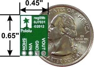
The output voltage is programmable through three feedback resistors connected from VOUT terminal to GND terminal.

I'd speculate if removed Rfb1, Rfb2 and R3 and replicated that layout externally, it would work the same. I'm looking over the schematic now to verify that.
Here are some that might work for you guys.
http://www.dimensionengineering.com/products/de-swadj3
http://www.dimensionengineering.com/products/de-sw033
http://www.dimensionengineering.com/products/de-sw050
I use these all the time: http://www.dimensionengineering.com/products/swadjhv
It looks like the efficiency ranges from 75% to 90% (under ideal conditions). I don’t think that stitching is on the final version:

I’d like to be proven wrong, but I just don’t see it sustaining two amps without a heatsink. I’ll send him a message and ask for some temperature data. 
By the way, you’re right, I guess I shouldn’t say “100% no way” as it is a bit hyperbolic, though I don’t really mean it in that way. It’s like literally.
Anyway, though the design is small, there are smaller and cheaper alternatives out there. I’ve got a couple of these and they work great, especially at $6 a pop.
1 Like
I have quite a few switching regulators that will run a constant 2 or 3 amps without a heatsink. They run warm but are designed for the current load.
@RWB Yes, but how big are they?
both about 1 inch square. Very compact.
Yeah, it’s totally possible with a thick board and large inductor. Got a picture of your boards or a link to where they’re sold? I actually could use a compact 3A switcher.
BTW, check your PMs! 
He doesn’t really say at what input voltage or what ambient temperature it will sustain 2A, but he does state it in several places that it will do 2A without a heatsink. With all of his technical data, I don’t see any reason to doubt him. One of his graphs shows it’s 90% efficient out to 2.125A, and 88% at 3A! with an input voltage of 7V. In fact it’s well above 80% for most input voltages. Only time it’s less than 80% is at lighter loads, which doesn’t matter anymore concerning power dissipation.

Yeah, true. I might just be jaded by all these knockoff power supplies from China (like the LM2596’s you can buy for $2 a pop).
Well if you want to make a good power supply and give it away, I’ll buy one 
No pictures but they are 2 and 3 amp switching regulators that output a regulated 5v output at 2 and 3 amps. One is a buck and one is a boost. Super small designs.
I bought a few of those chinese regulators you linked to below also and they work just fine. Although some of the chips may be knockoffs based on some testing others have done where the chip does not meet its rated specs.