Hi Guys,
I am Elco Jacobs, the founder of BrewPi, an Arduino and Raspberry Pi based brewing temperature controller.
I have just designed a PCB for a BrewPi Spark Shield and I would like to share it with you in hope you have some valuable feedback.
Here is some background info to help you understand some of the design choices:
Background
In BrewPi, the Arduino runs all temperature control independently and the Raspberry Pi is used for data logging and providing a web interface. The main reason for this is that the Pi can crash and the Arduino cannot: the beer is always safe.
The Arduino has been a good platform for a while, but we are outgrowing the platform in ROM and RAM space needed. The Spark core seems to be the most promising platform to upgrade to, mostly due to the active community behind it.
The on board WiFi fits with our goals of having a central server and multiple embedded controllers for various parts of the brewery. One of these devices is a fermentation fridge and another we are working on is a HERMS setup where the spark has to control pumps, heating elements, motorized ball valves, and pressure volume sensors. See http://www.homebrewtalk.com/f11/automated-closed-system-herms-layout-490798/
The key aspect for this new version of BrewPi will be modularity: our software will let you set up a physical model of your brewing setup and assign sensors and actuators for model predictive control.
For this reason, I have chosen to focus on bus protocols: the shield has only 3 digital pin outputs, all other devices have to connect through OneWire or RS-485.
This lets us connect many sensors and actuators. For example, the HERMS setup will have 12 motorized valves, 2 pumps, 2 heating elements and about 8 temperature sensors. I plan to daisy chain all of them to prevent wire spaghetti.
The shield design
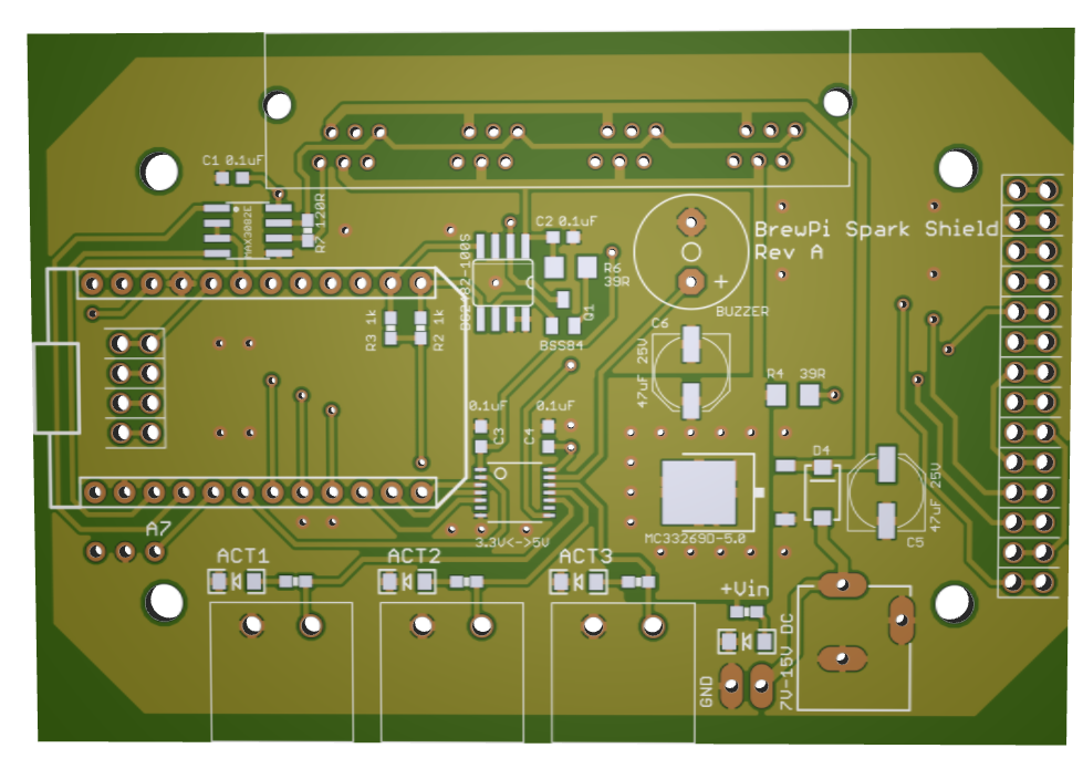
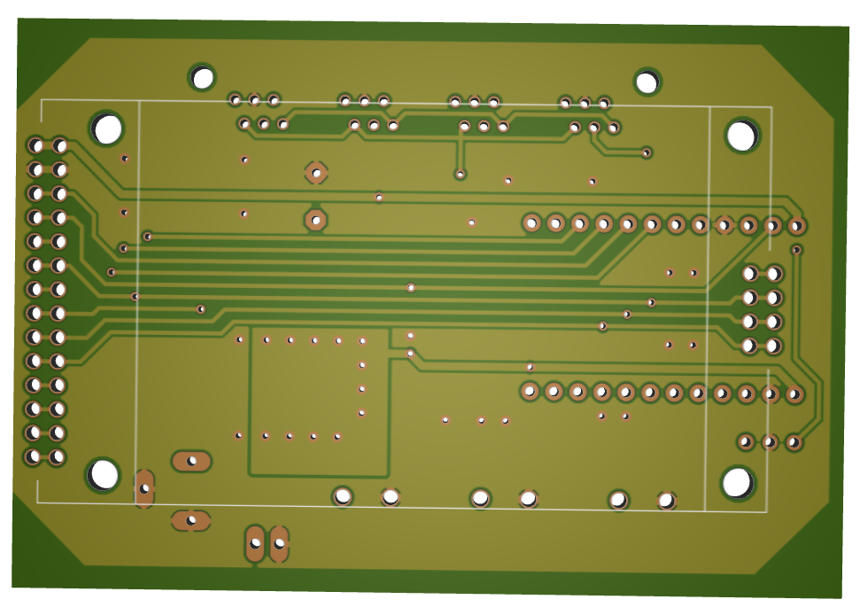
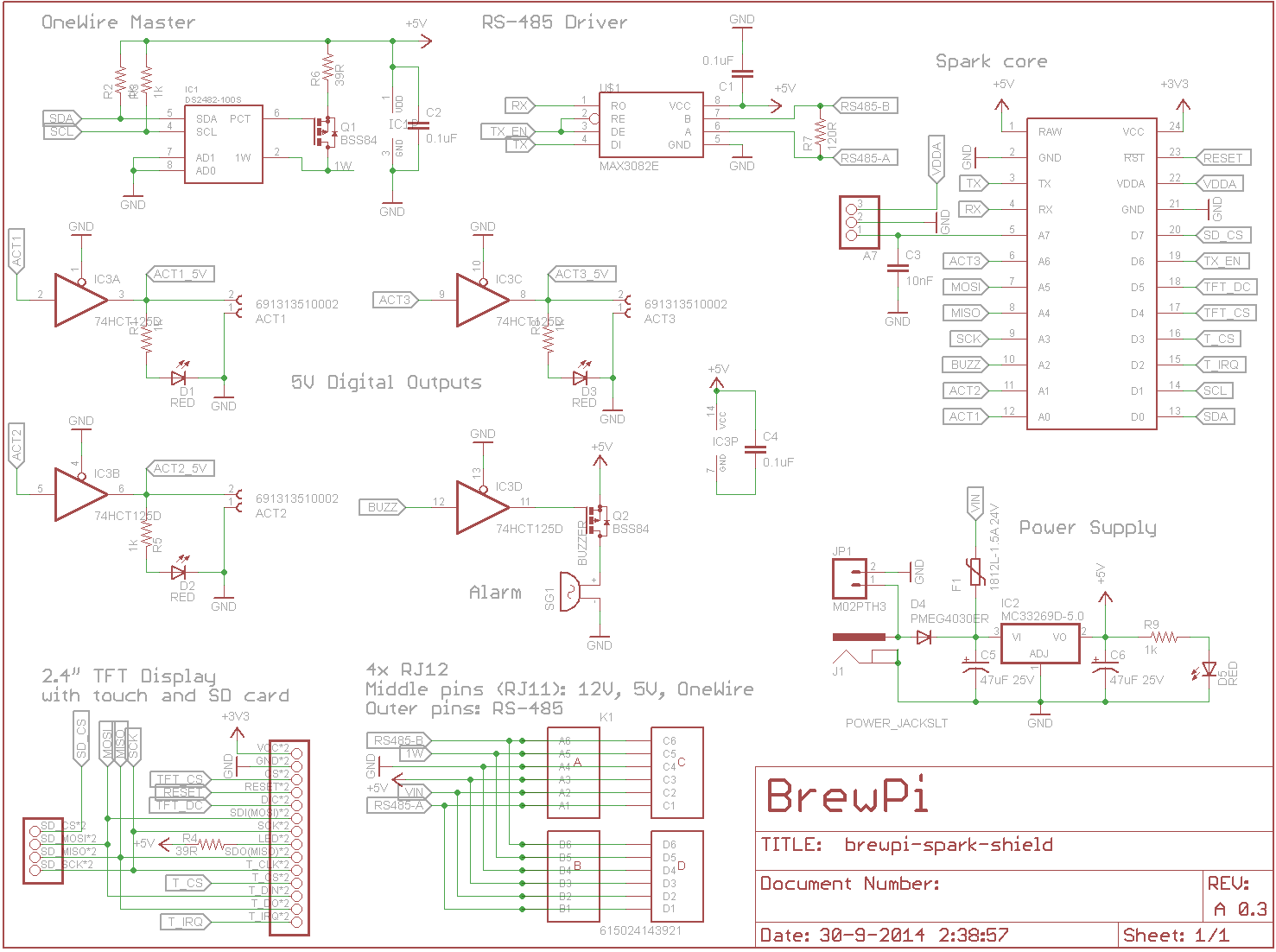
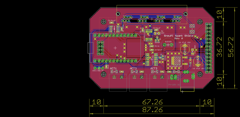
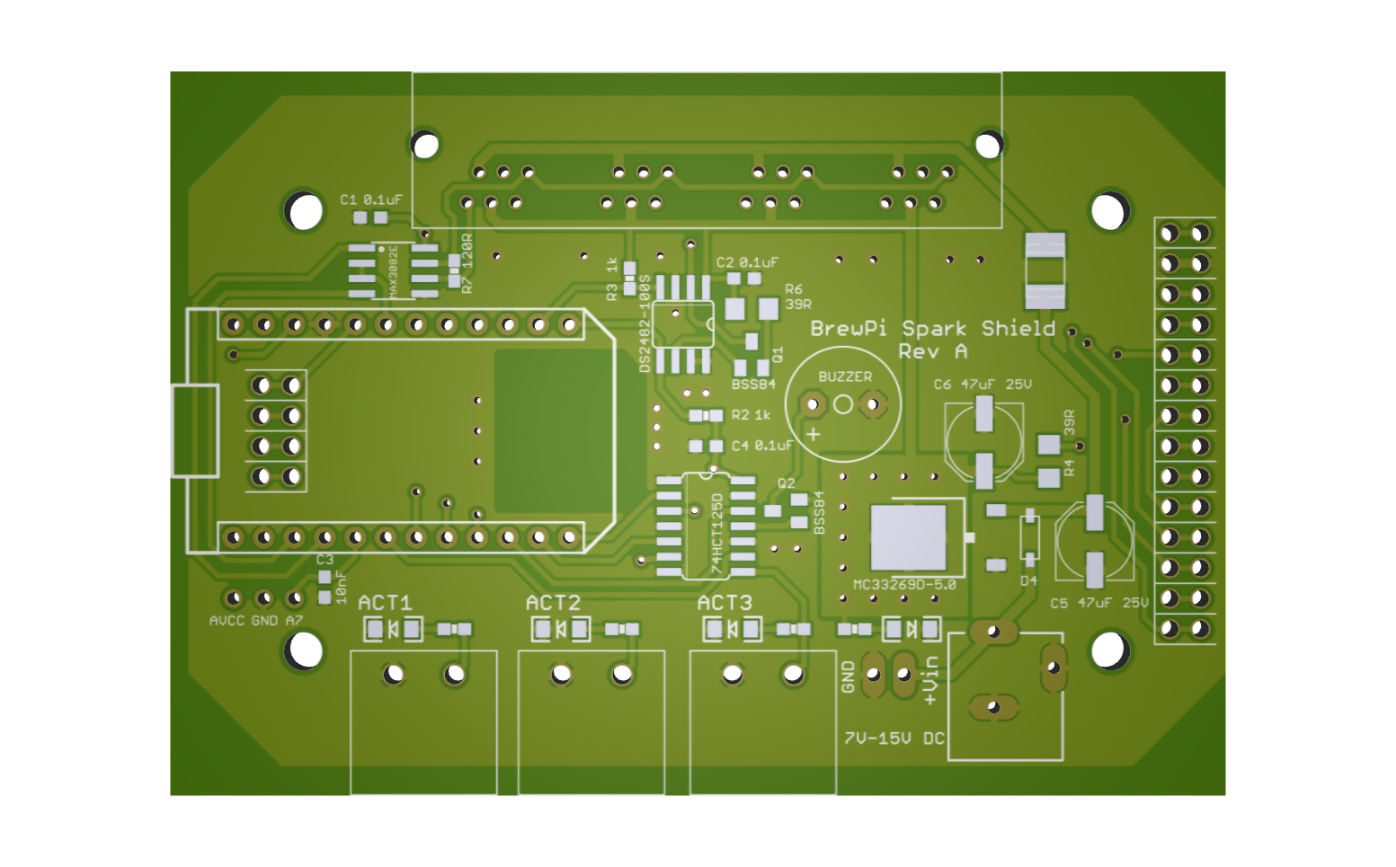
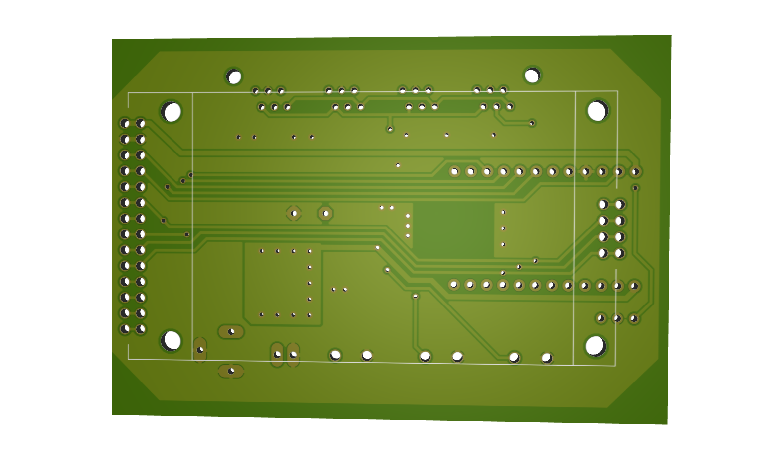
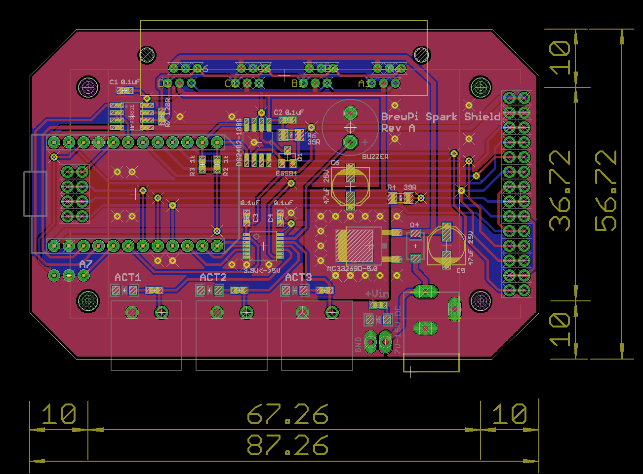
So here is the schematic, PCB layout and 2 board renders. It was quite a challenge to route this baby!
I changed the pin mapping continuously to try and prevent wires from crossing. The end result is pretty small (90x60mm), 2 layers, all components on one side, and display right in the middle.
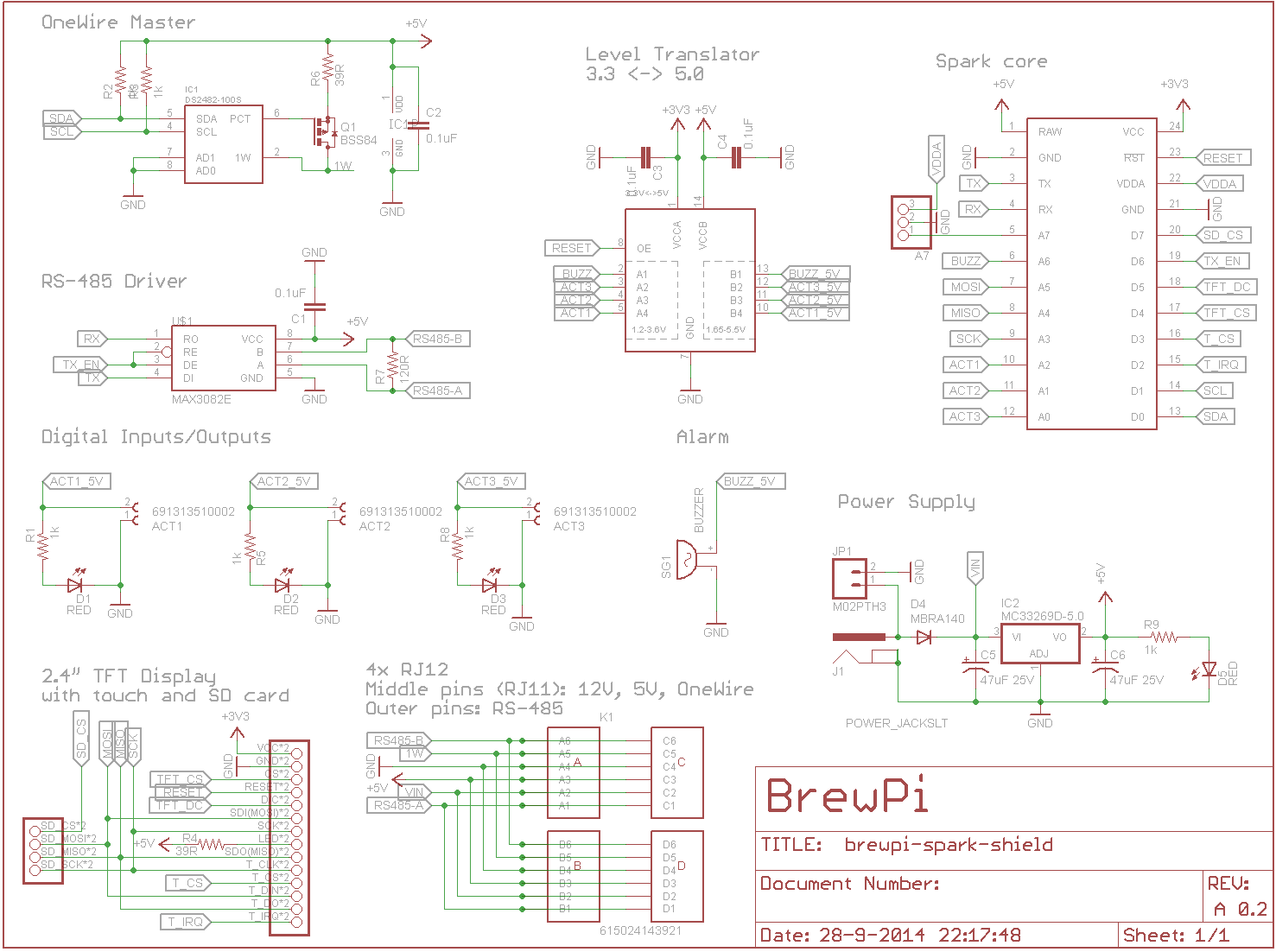
So what’s on the board?
Spark core
Of course, there are headers for the spark on board. We might switch to integrating one on the board later, but for now a shield works well. The spark is near the edge, so USB can still be used when this is in a casing.
TXB0104PWR Level shifter
The outputs are all 5V logic level, so I added a 4pin TXB0104PWR level shifter. This is the 4 pin version of the TXB0108PWR on the shield shield. I actually think the shield shield would be better with the TXS0108, because it supports pull-up resistors, which are required for I2C or 1-wire. It has lower output current per pin, but I think that’s less important than supporting 1-wire and I2C. I picked the TXB014PWR, because I decided to not route I2C off-board and I have a OneWire bus master on board.
DS2482-100 OneWire bus master
I decided to include a OneWire bus master with strong pullup. This will make the shield more robust in big OneWire networks and offload the core with the precise timing requirements. It will also provide 3.3->5V level shifting for more reliability. This chip is powered by 5V, but the SDA and SCL pins of the Spark are 5V tolerant.
MAX3082E RS-485 driver
We will be developing new sensors, for example pressure based volume sensors. To make it easy to use them (plug and play), they should be automatically discovered and have a standardized protocol. In other words: their own microcontroller. RS-485 is the most used multi-drop bus protocol to talk to other devices over long distances.
I picked the MAX3082E for the reduced slew rate (less interferance), fault safety (shorted or open), and ESD protection.
There is an on board 120 ohms resistor for line termination.
I have verified with Maxim that the MAX3082E can be driven by the 3.3V pins of the spark.
Digital inputs/outputs
Just 3, because of the bus protocols. I added an LED for easy debugging. I did not add snubber diodes, as most people using mechanical relays will use prefabbed pcb modules, which have snubbers on board. These outputs are more than fine for SSRs, with 5V, 50mA drive from the level shifter. I will use pluggable terminal blocks for these.
All 3 outputs are on a PWM pin of the spark.
A7 was left, so I added a header to have just 1 analog inputs for prototyping. I would like to give the board more analog inputs, but it was either level shifting or analog input capability.
Buzzer
A self-driven (internal oscillator) buzzer for alarms. The level translator drives the buzzer at 50mA, which should be enough.
TFT module with touch screen and SD card slot
I found this TFT, which seems to offer a lot of bang for buck: 2.4", 320x240, touch screen and SD card slot. All are driven by SPI and have their on chip select pin. The touch IRQ pin is on an interrupt pin of the spark (D2).
The display is powered by 3.3V from the spark, but the backlight LED is powered from 5V, to have a bit more voltage drop over the series LED for the backlight.
The display is mounted to the bottom of the shield, but I used Samtec BSW bottom entry headers, so all components are mounted on top of the board and the board can be assembled with SMT and reflow soldering. The pins insert into these headers through holes in the board.
4x RJ12 connector block
All 4 RJ12 connectors are connected in parallel (yay bus protocols!).
On the middle 4 pins, I have OneWire, GND, 5V, 12V. This should be enough to connect DS18B20 temperature sensors, OneWire thermocouple chips, DS2408/DS2413 chips to control ball valves, pumps, heating elements and other digital inputs and outputs. These can all have an RJ11 plug, which only connects to the middle 4 pins.
The outer pins have RS-485 for talking to other devices, so if a user plans to use RS-485, he can use RJ12 cabling instead of RJ11.
Power circuit
I copied the power circuit from the spark shields. I am still in doubt whether I should add a DC-DC converter instead. This supplies only 800mA, so the power that can be drawn from the 5V line is limited. It will also generate quite a bit of heat dropping down from the 12V input.
Most power hungry pheripherals will however be powered from the 12V line, like PC fans and the ball valves.
Typing this I just saw, I need a bigger diode than the MBRA140.
Reducing costs
The BrewPi Arduino shield was expensive to manufacture. Too many parts had to be soldered by hand, partly because there were components on both sides of the board.
It also had a lot of connectors on board. Some of those would never be used. What not many people realize is that connectors are the most expensive components, they cost much more that semiconductors.
By choosing bus protocols, limiting the amount of connectors and using cheap RJ12 connectors, I tried to limit costs this time. The board also only has 19 different components.
Conclusion
So that’s my design and the argumentation behind it. Please try to shoot a hole in my reasoning, don’t be kind. I would really appreciate some honest feedback.