Capacitance meter using the Photon

Anyone got any views on making a capacitor meter using the photon? I need to measure small capacitances.

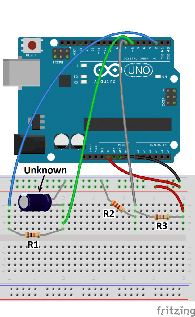
I like the third style on this page that just uses the Cap connected to the microprocessor

http://www.circuitbasics.com/how-to-make-an-arduino-capacitance-meter/

I would just output to the consol. From my tablet I cant read the code they used but it should be reasonably easy. Charge the cap then start a timer and read the cap.


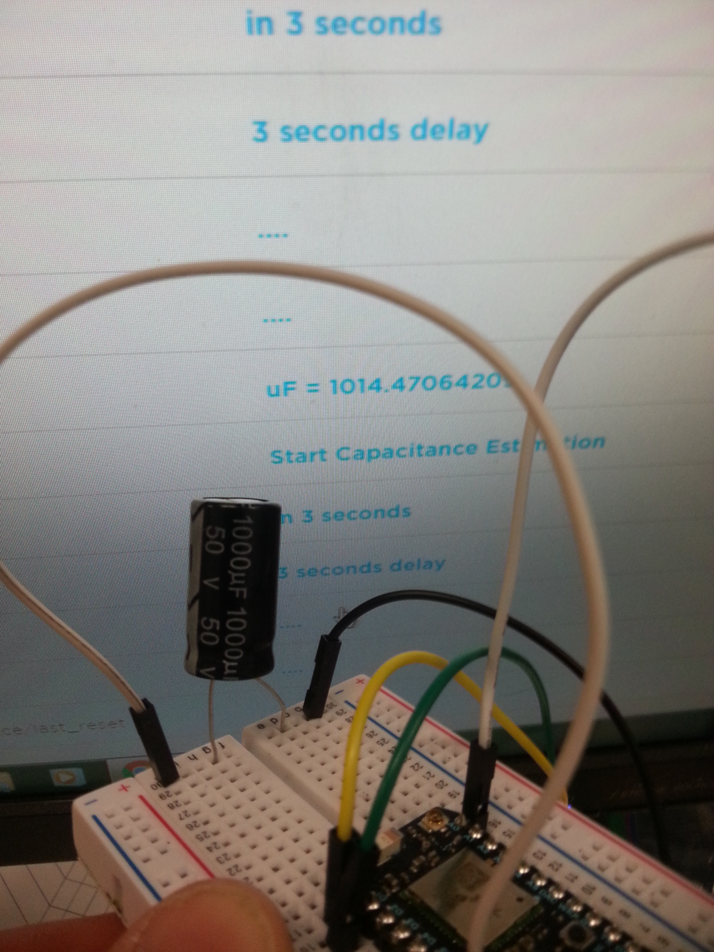
My tablet could not read the Arduino code but now I can I just have to change it for the console.

const int OUT_PIN = A2;
const int IN_PIN = A0;
const float IN_STRAY_CAP_TO_GND = 24.48;
const float IN_CAP_TO_GND  = IN_STRAY_CAP_TO_GND;
const float R_PULLUP = 34.8;  
const int MAX_ADC_VALUE = 1023;

void setup()
{
  pinMode(OUT_PIN, OUTPUT);
  pinMode(IN_PIN, OUTPUT);
  Serial.begin(9600);
}

void loop()
{
    pinMode(IN_PIN, INPUT);
    digitalWrite(OUT_PIN, HIGH);
    int val = analogRead(IN_PIN);
    digitalWrite(OUT_PIN, LOW);

    if (val < 1000)
    {
      pinMode(IN_PIN, OUTPUT);

      float capacitance = (float)val * IN_CAP_TO_GND / (float)(MAX_ADC_VALUE - val);

      Serial.print(F("Capacitance Value = "));
      Serial.print(capacitance, 3);
      Serial.print(F(" pF ("));
      Serial.print(val);
      Serial.println(F(") "));
    }
    else
    {
      pinMode(IN_PIN, OUTPUT);
      delay(1);
      pinMode(OUT_PIN, INPUT_PULLUP);
      unsigned long u1 = micros();
      unsigned long t;
      int digVal;

      do
      {
        digVal = digitalRead(OUT_PIN);
        unsigned long u2 = micros();
        t = u2 > u1 ? u2 - u1 : u1 - u2;
      } while ((digVal < 1) && (t < 400000L));

      pinMode(OUT_PIN, INPUT);  
      val = analogRead(OUT_PIN);
      digitalWrite(IN_PIN, HIGH);
      int dischargeTime = (int)(t / 1000L) * 5;
      delay(dischargeTime);   
      pinMode(OUT_PIN, OUTPUT);  
      digitalWrite(OUT_PIN, LOW);
      digitalWrite(IN_PIN, LOW);

      float capacitance = -(float)t / R_PULLUP
                              / log(1.0 - (float)val / (float)MAX_ADC_VALUE);

      Serial.print(F("Capacitance Value = "));
      if (capacitance > 1000.0)
      {
        Serial.print(capacitance / 1000.0, 2);
        Serial.print(F(" uF"));
      }
      else
      {
        Serial.print(capacitance, 2);
        Serial.print(F(" nF"));
      }

      Serial.print(F(" ("));
      Serial.print(digVal == 1 ? F("Normal") : F("HighVal"));
      Serial.print(F(", t= "));
      Serial.print(t);
      Serial.print(F(" us, ADC= "));
      Serial.print(val);
      Serial.println(F(")"));
    }
    while (millis() % 1000 != 0)
      ;    
}
2 Likes

I don’t have experience with that method but it seems to me that the discharge is done over a largely unknown resistor (the photon’s input pin). I.e., you can read the spec and see the expected input impedance but you will need to characterize it to get an accurate value. Secondly, if you want to measure small caps - are you talking picos? I would think you have to make your circuit very close to the input pins (don’t use bread board) to be fairly accurate.

Seems like a neat project though.

@rocksetta, you will need to adapt the values for a 3.3v system and for a 12-bit ADC. The input impedance of the ADC may impact the readings so you will want to a) Add a series resistor to the capacitor to slow the rise time and b) keep that resistor relatively low so the impedance effect is negligible (10K or less).

I am trying to read the impedance of the capacitors I am 3D Printing mentioned here:

The cap in question looks like this

so I am not sure if they are uF or pF.

I was wondering if things would be much different for the Photon than the Arduino, I might be able to tune the output in the software based on a few known input caps, or using @peekay123 resistor suggestion.

Two other possible diagrams might be better for the Photon.

The basic one

The more accurate one

Both are from the previous metioned site

http://www.circuitbasics.com/how-to-make-an-arduino-capacitance-meter/

I really like the simple arrangement, possibly with @peekay123 suggestions of a resistor. Any reason to use the other arraignments?

@rocksetta, your 3d printed capacitor will most likely have a capacitance in the pico farad range. Second, “impedance” is the frequency-domain resistance of a device, not capacitance. So, which are you trying to measure?

Sorry capacitance is what I want.

const float IN_STRAY_CAP_TO_GND = 24.48;
const float IN_CAP_TO_GND  = IN_STRAY_CAP_TO_GND;
const float R_PULLUP = 34.8;  
const int MAX_ADC_VALUE = 1023;

The Arduino code mentions these variables. Any suggestions for Photon values?

@rocksetta, you’ll need to dig through the STM32F2xx datasheet for the stray capacitance to ground, which may be a problem since, unlike Arduino, the STM32 doesn’t have a front-end buffer on the analog input. Unless you add a buffer (unity gain op-amp), you may want to consider sticking with an Arduino.

Sorry @peekay123 I stick to the PI or Photon. So looking at the situation with the 3 resistors. Here is the code. I am a bit confused by the code which does not compile. Can someone explain the ISR (looks like an interrupt) and what is all the:

ADCSRB = 0; ACSR = _BV (ACI) | _BV (ACIE) | _BV (ACIS0) | _BV (ACIS1);

. Looks to me like an include file is missing.

Here is the complete code:

    const byte pulsePin = 2;
    const unsigned long resistance = 10000;

    volatile boolean triggered;
    volatile boolean active;
    volatile unsigned long startTime;
    volatile unsigned long duration;

    ISR (ANALOG_COMP_vect)
      {
      unsigned long now = micros ();
      if (active)
        {
        duration = now - startTime;
        triggered = true;
        digitalWrite (pulsePin, LOW); 
        }
      }

    void setup ()
      {
      pinMode(pulsePin, OUTPUT);
      digitalWrite(pulsePin, LOW);
      Serial.begin(9600);
      Serial.println("Started.");
      ADCSRB = 0;          
      ACSR =  _BV (ACI)     
            | _BV (ACIE)    
            | _BV (ACIS0) | _BV (ACIS1);  
       }  

    void loop ()
      {
      if (!active)
        {
        active = true;
        triggered = false;
        digitalWrite (pulsePin, HIGH); 
        startTime = micros ();  
        }

      if (active && triggered)
        {
        active = false;
        Serial.print ("Capacitance = ");
        Serial.print (duration * 1000 / resistance);
        Serial.println (" nF");
        triggered = false;
        delay (3000);
        }
    }

This needs to be set to 4095 (=12bit ADC as @peekay123 pointed out earlier)

And some of that code is rather hardware specific to the AVR chips, so that won't work at all.

see here for what the code does
http://www.fiz-ix.com/2012/01/introduction-to-arduino-interrupts-and-the-atmega328-analog-comparator/

oooooo… I am out of my league.

Thanks @ScruffR, @joost and @peekay123 If anyone wants to write some code to use the Photon to measure capacitance please put the code here.

I think I am going to purchase a $15 USD capacitance multimeter like https://www.amazon.com/Multimeter-Capacitance-Resistance-Continuity-Transistor/dp/B00Y245JRE/ref=sr_1_2?ie=UTF8&qid=1495114150&sr=8-2&keywords=multimeter+capacitance anyone know of a better but cheap one?

Strangely capacitance multimeters cost about $70 CDN in our local stores and I don’t think that is because of the US/Canadian exchange rate :relaxed:

@rocksetta, some of these use an ATMega328!

https://www.amazon.com/s/ref=nb_sb_noss_2?url=search-alias%3Daps&field-keywords=328+tester&rh=i%3Aaps%2Ck%3A328+tester

@rocksetta; the multimeter you referenced has only a 2uF lowest setting - might be a little difficult to measure your caps in the pF range. If all you need is a cap measurement, for little money, perhaps this one will do: https://www.amazon.com/Honeytek-A6013L-Capacitor-Tester/dp/B0036FQ3FW/ref=pd_cp_469_1?_encoding=UTF8&pd_rd_i=B0036FQ3FW&pd_rd_r=ZSGATJRMW37W08S42JVY&pd_rd_w=HSnJb&pd_rd_wg=ErbwX&psc=1&refRID=ZSGATJRMW37W08S42JVY

I have no experience with this device, no idea about quality and workmanship but for 16 bucks…

1 Like

So when I don’t understand other peoples programs I make my own :slight_smile:

Seems to be working. I just have to tweak a few values. My working range at the moment seems to be about 500 uF to 0.005 uF, possibly more, I just don’t have capacitors that big or small to test.

1 Like

Using the basic 2 resistor Arduino setup.

GND to capacitor (either terminal seems fine)
Then the other side of the capacitor to 3 connections:

  1. large 100 K ohm resistor to D0 (charging)
  2. small 1 K resistor to D1 (discharging)
  3. Connection to A0 (analog reading)

I know that for capacitors the capacitance varies directly with the time to charge and inversely with resistance

So I picked an analog measurement (1000) as a cutoff to say that it is sort of charged.

Most science equations have a constant to adjust for real data. So I just hooked up several known capacitors and looked for the adjusting constant.

Capcitance = unknown constant x time / resistance

and hoped for a linear equation.

P.S. Found https://mycurvefit.com/ just in case it wasn't linear. What a wonderful data to equation website

Here is my final results for these capacitors:

0.02 uF
0.1 uF
100 uF
470 uF

The large number of digits allowed me to not worry about nF, uF or pF (Kind of lousy science for significant digits. :grinning:)

Here is my code:

//Capacitance Esitmation
// Photon
// By Jeremy Ellis May 2017
// MIT license

// GND to capacitor neg terminal (Doesn't seem to matter which terminal is GND and POSITIVE)
// capacitor Positive terminal to the following 3 items:
// large 100 K ohm resistor to DO (charging circuit)
// small 1K ohm resitor to D1 (discharge circuit)
// wire to A0 (Analog read circuit)

int mainResistor = 100000; main resistor 100 K ohm
int A0Cutoff = 1000; // 648
//float myConstant = 3.40; works with 100 k ohm resistance and lower

// where capacitance = Correction amount * timeConstant / resistance of circuit

unsigned long startTime;
unsigned long elapsedTime;
float microFarads;

void setup(){

pinMode(D0, OUTPUT);

}

void loop(){

digitalWrite(D0, LOW);   // stop charging the capacitor
pinMode(D1, OUTPUT);            
digitalWrite(D1, LOW);          // discharge the Capacitor
Particle.publish("Discharging","....", 60, PRIVATE);

while(analogRead(A0) >20){     // wait until signal is low enough
   // do nothing while waiting  may cause an error if too long a wait
}
delay(1000);  //wait a bit longer
pinMode(D1, INPUT);       // stop discharging the capacitor
Particle.publish("Discharged","....", 60, PRIVATE);
Particle.publish("Disconnect?","3 seconds delay", 60, PRIVATE);
delay(3000);
Particle.publish("Starting","in 3 seconds", 60, PRIVATE);
delay(3000);
Particle.publish("EVENT","Start Capacitance Estimation", 60, PRIVATE);
digitalWrite(D0, HIGH);  // start charging the capacitor
startTime = micros();    // stop the clock

while(analogRead(A0) < A0Cutoff){ // wait until signal is high enough
   // do nothing while waiting  
}
elapsedTime= micros() - startTime;    //why use milliseconds when you canuse micorseconds
microFarads = myConstant * ((float)elapsedTime / ( mainResistor) )  ;  // the big cacluation

Particle.publish("Time (us) " + String(elapsedTime),"uF =  " + String(microFarads, 8), 60, PRIVATE);
delay(2000);
// microseconds may overload long inteeger with large capacitors!!

}

Theoretically if a time of 627 micro-seconds = 0.213 uF then a time of 1 micro-second would equal a lower limit of 0.00003 uF.

As far as an upper limit. An unsigned long data type can store 4,294,967,295 integers so the upper limit might be 146,000 uF which may take a very long time to analyse (I think slightly over an hour!).

So theoretically this process should be able to measure the capacitance from 0.00003 uF to 146,000 uF.
or
30 pF to 0.146 F

Fairly sure it doesn't. :slight_smile:

....

I just tested a 1000 uF capacitor and it did not work. The photon complained bythe LED switching to solid green?

Here are my 3D Printed capacitors

Strangely both start at 0.003 uF that may be my bottom limit. Perhaps the loop function can't loop faster than 90 us

2 Likes

So I found some bigger and smaller capacitors, but they don’t work. 1000 uF kills the photon (Solid green LED) and anything below 0.003 uF just reads as 0.003 uF. So, next week I am going to test them using a smaller resistor than the 100 K ohm charging resistor for capacitors larger than 500 uF (If the photon gives a solid green LED) and a larger resistor for any capacitors that are smaller than 0.003 uF (3000 pF) or whenever the photon reads 0.003 uF.

Had to look up how to read those really small caps. Looks like a really small cap is read in pF and numbers like 142 would be 1400 pF. The last number being the number of zeros. (Some small caps have color bands but I don’t have any of those.)

A link about small Caps

Looks like the color bands can get really confusing so here is a chart that makes it look even more confusing. :relaxed:

http://www.electro-tech-online.com/attachments/capacitor_conversion_chart-gif.6935/

Personally I just like to test stuff and see what I get. I will post when I get some results for bigger and smaller capacitors.

1 Like

So I changed the charging Resistor from 100 K ohm to 5.1 K ohm and managed to charge a 1000 uF Cap and got a reading of 1014 uF Not Bad. Did not have to change my constant value at all.

So I tried using a 500 k ohm resistor so that I can charge small capacitors and it looks like it works as well.

A 683 Small cap which I think translates to 68000 pF or 0.068 uF, read 0.081 uF which is a bit off but at least in the correct ball park. What I was really pleased about is that my constant also did not need to be changed when I tested both the 0.1 uF and 0.02 uF capacitors. Can’t do much more with this until I get some smaller capacitors.

Sorry the pic is a bit blurry.

2 Likes

So I strung 7 x 470 K ohm resistors together to make 3290 K ohm resistance. Changed the value in my code and tested a 50 pF capacitor = 0.000050 uF

and without re-calibrating the program I managed to get a reading of 0.000185 uF (185 pF) which is not very good, however it was stable so if I did recalibrate a constant using known 100 pF and 20 pF capacitorsI think the values would be excellent.

Unless anyone has anything to add, I think this little study is done.

1 Like

I just wanted to make sure you understand that the capacitors you have been testing (at least the ones in the photos) are generally either +/-10 or 20%. A lot of electrolytic caps (like your 1000uF) are spec’ed at -20%, +80% since in the intended use bigger is generally better.

That means that your reading of 0.081uF for the cap labeled 0.068uF might have been correct and within a +20% tolerance.

Unless you spend a lot of money on mylar or silver-mica capacitors etc., these are not precision components. If you are selecting parts to compare the values of from a large batch using a capacitance meter (which also has some tolerance but is probably +/-0.5%), that sounds OK. Otherwise it hard to do good work without a reference.

1 Like

Interesting reading. It looks like your speculation about the loop time being 90us might be correct. I see timings of 90, 179, 627 and 3037 as being fairly close to being multiples of 90. That’s insignificant for the longer durations but does mean that shorter readings will be rounded up.
For small capacitances and very high charging resistors I wonder whether the input impedance of A2 becomes significant? It’s not something I’m familiar with, but perhaps others on the forum can comment?

1 Like

It probably does but would not be relevant if you calibrate around the size of your unknown capacitor. Once you have a ball park 600 uF or 0.00004 uF then get some known capacitors in that area and calibrate the constant, it should be fairly accurate. If I didn't have other projects I would probably work out how the calibration changes as your charging resistor changes.

example
float myConstant = 3.40; // when charging resistor <= 100 k ohm

float myConstant = 5.40; // when charging resistor >= 1000 k ohm.

Better would be to work out an equation for how the constant changes as the user changes the resistance. Even better than that would be to auto switch the resistance (using a ffew transistors) based on a test run to see how many micro seconds the analysis is taking. 90 us switch to higher resistance. If however the time was greater than 100,000 us then auto switch to lower resistance and re-analyse.

That is really interesting and does bring a significant error at the low end. So timings close to 90 us should be avoided as much as possible. Probably above 5000 us has little effect.

The top end seems to be somewhere above 13,000,000 (us) since 13,000,000 (us) worked for a 470 K ohm capacitor but 1000 K Ohm Cap wouldn't

@bko @timx any idea why the Photon dies above 13,000,000 microseconds (Photon gets a solid green main LED)