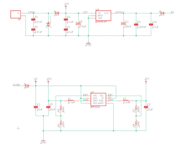
I am designing a carrier board for the B-series B324 module. My input to the system is 12V, and I want to have the simplest and most compact design possible. As far as I can see from the datasheet, I need both 3.3V and 3.8V PSU to power the B324 module. Is it not possible to use a single voltage connected to VCC? And is the max VCC only 4.3? It would be neat to have a 12V-5V or 12V-3.3V converter connected to VCC since these are much more common.
You need both voltages. The reason is that the MCU is designed to run at 3.3V (absolute maximum 3.6V), and the cellular modem requires 3.8V (3.7V to 4.2V).
The cellular modem requires the highest current (2A) so if you are building a custom power supply, going from 12V to 3.8V is one option, then add a small regulator for 3.3V after that. The XCL223/XCL224 are what we use on the Boron and I like that chip because it only requires input and output capacitors, no inductor required, and it’s tiny and inexpensive.
The other option is to go from 12V to 5V, because that’s a commonly available off-the-shelf configuration. Then have two regulators to 3.8V and 3.3V, or a dual regulator that does both. This is a design that I used for automotive use with a very durable 12V to 5V supply, and a MP2122 dual-output supply that supplies both 3.3V and 3.8V from 5V.
The MP2122 is the regulator used in the SoM First Board tutorial.
The 12V to 5V part of the design is from the Vehicle Power App Note.
This topic was automatically closed 182 days after the last reply. New replies are no longer allowed.
