For some reason after I plug in the device, the first thing that is supposed to happens (and does) is the Neopixel run through all the colors and then turns off until someone touches the button. However, after the Neopixel runs through all the colors and shuts down, the Photon stops breathing Cyan and gives me a solid cyan light and nothing can be done including flashing the photon. If I press the Adafruit LED arcade button a few times while its running through those colors and still breathing cyan, usually I can get it to continue breathing Cyan, but they still don’t work perfectly even after that.
At first I thought it had to be the code, but I have a few built with regular buttons that do not have an LED light and they work just fine. So, a minute ago I cut the the VIN and GND wire going to the Arcade button’s LED light on a couple of them and it works perfectly! I thought ok maybe there is something weird happening between the Neopixel and the Arcade button’s LED both being soldered to the VIN and GND, so I soldered the Arcade button LED’s power and GND wires into 3V3 and a different GND pin on the Photon and the exact same thing happens! I’ve tried changing the Photon’s firmware too and that didn’t seem to make a difference either. Its also not the PCB board either, I’ve used different brands and types with same issue. It really sucks because I blew through 3 photons before I realized it wasn’t a hardware or my crappy soldering that was creating the problem.
Anyone have any idea how I can fix this?? If I have to I’ll cut the power to the Arcade buttons LED but I really like the idea that the buttons LED will always be the same color of that specific lamp no matter what color the lamp itself changes to. Sorry to be wordy but I wanted to be as detailed as I could.
I GREATLY APPRECIATE ANY HELP! I’ve been working on this for almost a year lol.
EDIT: FYI, the arcade button LED works, thats not the problem. The problem is that the LED on the Arcade button is messing up the function of the Photon for some reason.
@Scottwd
When you have got a problem like this it is a good idea to post the schematic (electrical connections) and you code if you want the community to respond/review.
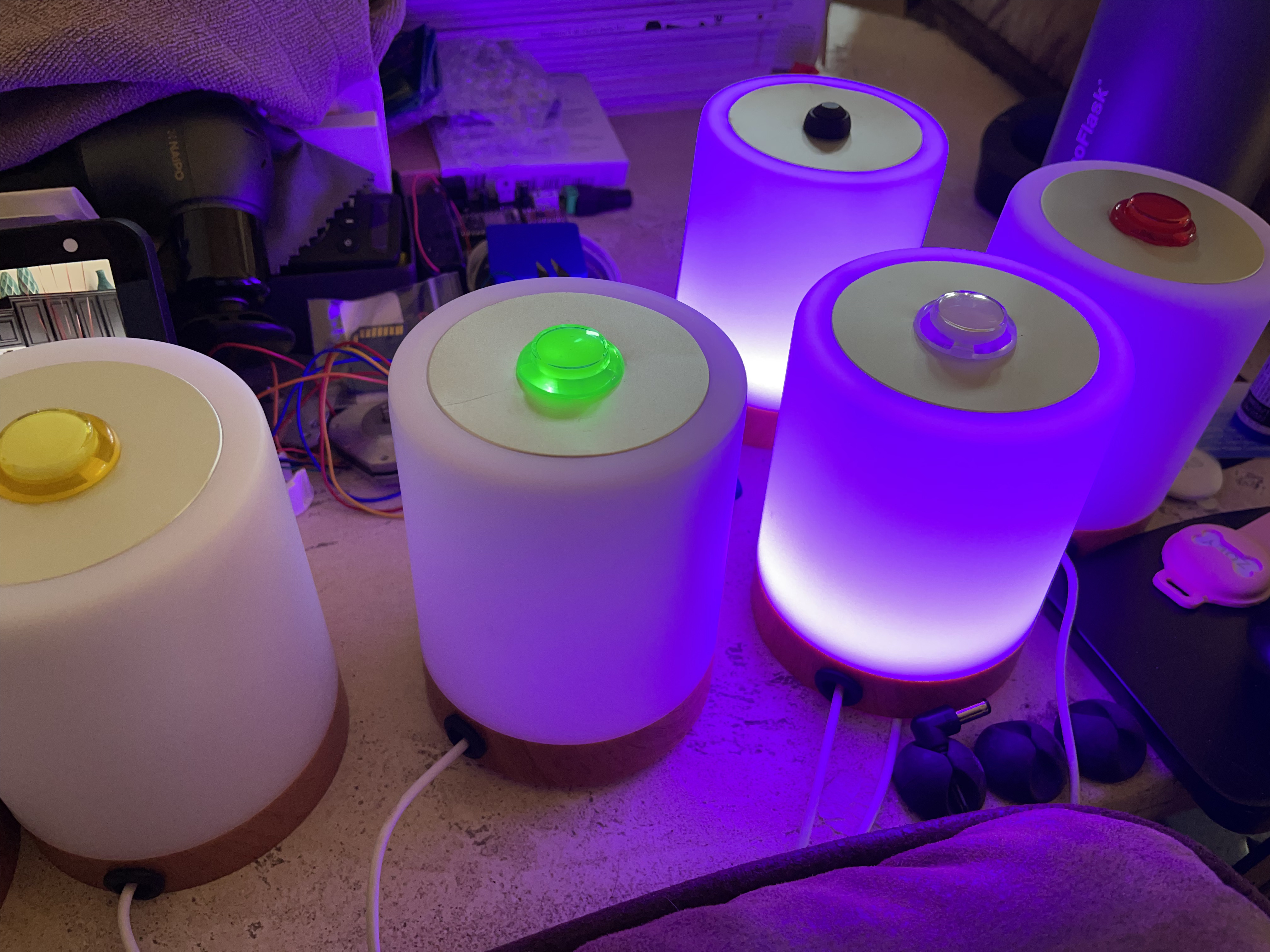
The Neopixel ring will require a good 5V supply to work - this means one that can supply sufficient current to enable all the LEDs to be lit at the same time on full power. I think from memory each RGB led in a Pixel draws 20mA when fully on so each RGB pixel takes 60mA x number of pixels in the ring (can’t see from your photo - but assume 24) that’s 60x24=1440mA. The Vin pin on the Photon cannot supply that - thus you may be getting a brownout with the voltage on the Photon. There are some ways around this;
Add a large electrolytic capacitor across Vin and GND - say 100uF/16V to act as a buffer store to ensure the Vin doesn’t get dragged down as the LEDs turn on and off.
Have your microUSB plug go to a socket not the Photon’s microUSB. Then connect the VBUS and GND to Vin and GND on the Photon and to power the Neopixel ring - I would still add a capacitor.
The signal output from the Photon is 3V3 - this typically isn’t sufficient to drive any significant number of NEOPIXELs - a level shifter should be used to change the 3V3 signal to a 5V signal.
Hope that helps and sorry about the blown Photons - likely only the signal pin.
Thank you so much for the response. I’m pretty new to hardware and not great with it haha. Sorry about not posting a schematic and the code is pretty long, but I will post that too I’m just having trouble being able to post that file? I’m not great at making a schematic so hopefully a fritz is good, its a fairly simple connection.
So, I thought the Photon’s were fried, they weren’t. They kept getting hung up after a few seconds of connecting to wifi and then I’d get a solid Cyan and the Photon would freeze.
The problem is only when that Arcade Button LED is connected to VIN. As soon as I disconnect the the LED part of the Arcade button everything works fine, including the Neopixels. They seem to be powered fine from Photon VIN with the MicroUSB…
As you can see in the second Breadboard design and Schematic I connected the Arcade Button LED’s to 3V3 and it lights up the LED Button fine and at first that light did the exact same thing and froze a few seconds after connecting to wifi (solid Cyan led on photon) but since then it seems to be working ok. Maybe I’ll add a capacitor too. The code is mainly from the post for making these, I didn’t change anything, the only thing different in the hardware is I decided to add the arcade button with an LED on it instead of just a regular switch button…
I couldn’t find the exact Adafruit Arcade Button, but this is close, but there is no 5th pin on the LED button.
@armor one last question…I don’t know a ton about capacitors, all I have are 10uF/50v. Is that too big, will it be ok to use those or should I just wait and buy some smaller? Thanks again for any help!
@Scottwd The trouble with following someone else’s design is that you need to understand it and also be able to spot when it is wrong. I suggest a bit of google research for example circuits.
There are 4 things wrong with the Fritzing breadboard views (nothing wrong with Fritzing as a tool) just the wiring or schematic of the circuit IMHO.
the switch - the common is connected to D3 and NO (normally open) is connected to D4. I can imagine how the code for this might work but it is not the recommended way to read a button state (pressed or not). I would rather use a resistor-capacitor combination to debounce the switch output like this
Suggest you check the datasheet for the Photon for pin Vin - the supply from the USB PSU should go directly to the Neopixel ring and not via the Photon.
@Scottwd, since we don't know whether you used the code of the linked project as is or not it's hard to properly advise.
However, the original project is using capacitive touch detection and no physical switch as your schematic suggest you do.
Hence all the logic of the cap-touch charge and measure logic will not apply to your setup and hence it's quite likely that that part is what's deadlocking your code.
Sorry I posted the wrong link. He has one with a button as well, the only thing I added was the button with an LED which I thought was low powered enough to be wired to the photon.
Here is the code, make sure branch is manual-switch