I am using a Boron as an asset tracker. I also need to connect to equipment over serial while using the serial-based GPS. I know this is not a novel problem. to keep the form factor small, I am using a Mikroe SC16IS740IPW that is two boards in one + the DB9 connnector. It is the SC16IS740 that we know and love for solving this problem, mated to a UART to RS-232 transceiver. It speaks I2C and SPI. Pretty handy for ~$20.
Here are the problems. 1st, you change between i2c and SPI modes by desoldering five SMD jumpers. That is a pain. So, I am trying to get SPI working. I am connecting it the same way you would the SC16IS750 purple board that folks are using.
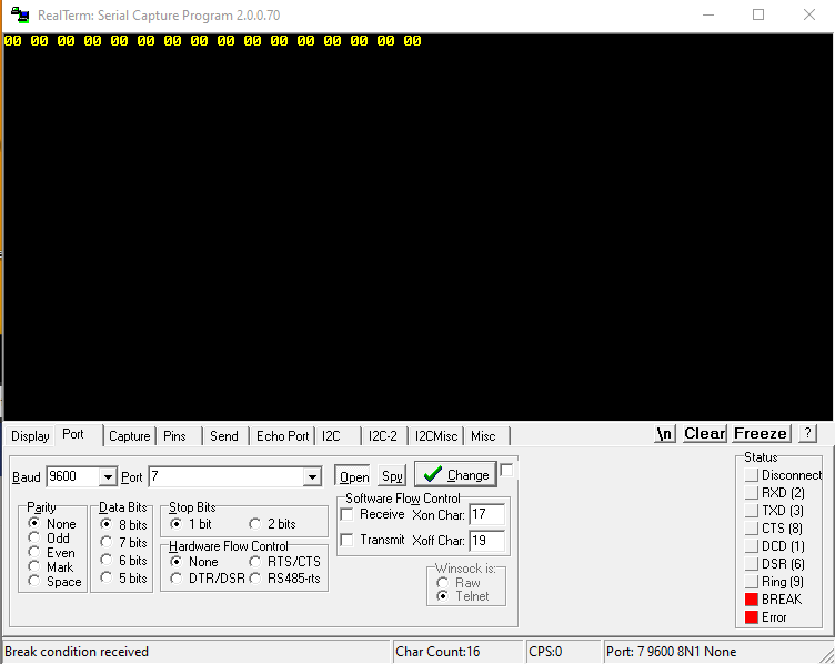
How it’s acting…
It is sending binary 00000000 to my USB to RS-232 adapter every 5 seconds.
The green light flashes quickly constantly on the Boron, as I have no reception in my lab in the basement.
The other Serial and Serial1 don’t seem to send anything out as I am also monitoring them. They should be sending something every second.
RealTerm is showing a solid “BREAK” in the Status.
I think you need to flip MI/MO.
MasterIn should connect to the SlaveDataOut (SlaveOut on the chip itself) on the Clickboard while MasterOut would send SlaveDataIn(to) (SlaveIn on the chip itself) the device.
Thanks for the help. I thought the MO was short for MISO (Master In, Slave Out) and MI was short for MOSI (Master Out, Slave In). I see now, that I was backward on that one; too many O’s and I’s I switched them up and now it doesn’t send anything. I am still getting the “BREAK” status.
Should the CS on the Clickboard be connected to the Borons’ A5 or A2? What is the purpose of the A2 in the line:
SC16IS740SPI extSerial(SPI, A2);
Also, I used Mariano’s advice and was able to easily move the jumpers over using two soldering irons with fine tips. Very gangster. Now, I can set up another Boron to try to use the Clickboard in i2c as originally intended. I still want to try to get this SPI working in case the i2c doesn’t cooperate.
Since SPI uses a distinct SS line for each individual slave that parameter indicates which GPIO is used to activate that specific sensor.
A5 might be the default SS line on the Boron you don't need to use exactly that but can choose whatever you want as long it is not used otherwise.
I owe you a beer!!! I moved the CS pin from A5 to A2, rebooted and I am in business!!
I read that the SS line had to be dedicated to the SS function and not be used by anything else. I have seen when working with over boards they will say you can’t use pin X for anything because a library is using it, but that is because it is being mapped internally, not because the pin is physically being used.
I didn’t realize that was the actual pin to connect to the slaves CS. That is why I was confused. Of course it can’t be used by anything else if I am using it for that. That is a redundant statement. That is like saying I can’t also use a SerialSoftware DA port for something else like a motor controller.
That is normal as the base address is only 7 bit but shifted left one bit where the bottom bit becomes the read/write bit.
You see the X in the table? That is where the direction bit would be.
When you take that bit out (shift right by 1) you will find all addresses will fall into the 0x00 to 0x7F range.
Thank you. So, my 144 becomes a 72. I’m not sure how to follow Rikkas’ directions in his Readme.
" public SC16IS740(TwoWire & wire,int addr,int intPin)
Construct the UART object. Typically done as a global variable.
Parameters
wire The I2C port to use, typically Wire.
addr The address you’ve set using the A0 and A1 pins, 0-3. This will be converted to the appropriate I2C address. Or you can directly specify the actual I2C address 0-127."
He doesn’t say if it should be in decimal or hex or what, although I do see it says 0-127. I’ve tried
So, it works! Thank you so much for being so tenacious with helping on HW you don’t even make. This allows me to move forward for Particle on this solution.
After my first flashing attempt I put it into a 10 blink red SOS state. That was caused by Win10 file location protections breaking things. So, that was fun to fix LOL. I now write locally, cloud compile, and local flash. That is the fastest and most consistent for me.
Point is, I needed to pull the power altogether after the flash and it started working.
Thank you so much for your help. I can now move on to other challenges and get this put together.


 I switched them up and now it doesn’t send anything. I am still getting the “BREAK” status.
 Now, I can set up another Boron to try to use the Clickboard in i2c as originally intended. I still want to try to get this SPI working in case the i2c doesn’t cooperate.

