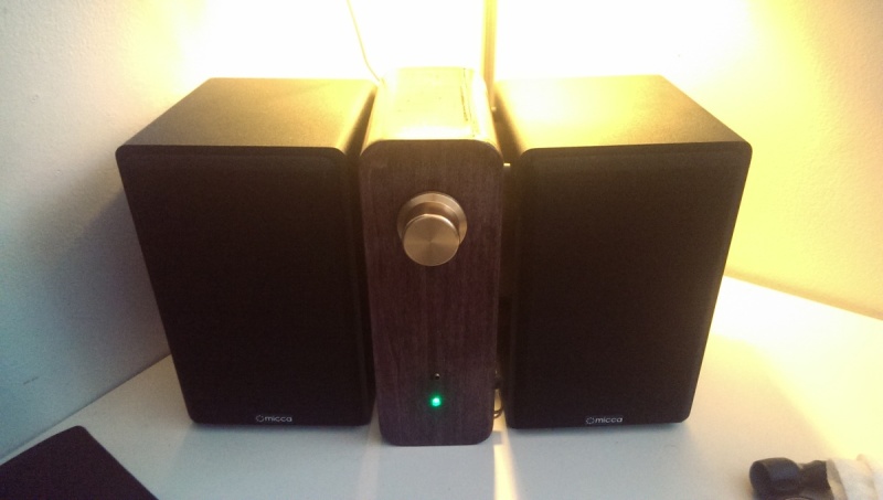
I’ve been working on a Spark controlled FM radio + audio amplifier for quite a while, and I’m to a point where I’m in over my head. Functionally things are working pretty well, but I’m getting microcontroller noise (pops, clicks, hums, screeches, etc) behind the amplified audio signal. I’m not a hardware guy, and I’m doing all this through a research then trial-and-error approach.
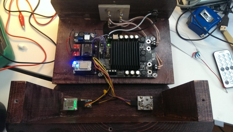
Designed myself a little “motherboard” of sorts to get the Core, FM, and Pot close together and easily mountable in a box. It connects the components together but also exposes a bunch of headers to connect external buttons/leds/rotary encoder, etc.
I have a few questions I was hoping someone might be able to help me with.
The digital potentiometer calls for an analog ground, which the document states that GND and AGND should be tied to the same voltage level. Where should that special AGND be coming from?
I’ve recently been working on isolating the audio components from the Spark Core by using a separate power supply and an optoisolator. I am not able to figure out how to isolate the FM board since it requires serial communication, and when I power the FM board separately, the serial communication does not function. How can I isolate the Spark Core and the FM board electrically if they must connect for serial communication?
And generally are there any other things I can do to reduce the microcontroller noise out of my audio signal? I have been at this for close to a year and I’d like to get on with it. (My plans are to put these in every room of the house)
That is a very cool project! I really like the idea and the implementation.
Whenever you combine digital and analog electronics there can be problems and audio signals are tough because our ears pick out every flaw.
You have the possibility of both conducted (along a wire) and radiated (through the air) noise being injected into your system.
You should try to find the sources of noise in your system. Try disconnecting the inputs to the amplifier and grounding them at the amp and then grounding them at the FM board. Try by-passing the volume control parts temporarily too. Once you find the sources of noise, it will be a lot easier to fix them.
Some ideas:
The analog and digital grounds should be tied together in only one place as close to the power source as practical.
The analog and digital power supply leads should be on separate supplies if possible or filtered individually with capacitors and possibly a ferrite bead or ring, and split off right at the power supply output.
Low level analog signals like your audio inputs to the amp should be routed away from digital using short wires if practical.
If you can’t physically move the low level analog wires, you should shield them. You can use ordinary RCA cables which are coax typically. You may find it better to only ground the shield at one end since the FM board and the amp should be tied together at the analog ground point near the power source.
It looks like you have a switching power supply or two to reduce the input power supply to 5V for the core. A linear supply might be better and could reduce noise, but if you want to use this type of supply you need to filter the output of the supply with at least some capacitors (electrolytic and ceramic). You may also find a ferrite bead or ring will help.
You have the Spark core antenna oriented toward the amplifier. You should move the RF sources away from the lower level audio signals. If you can’t move it, you should shield the audio section and low-level signals with a Faraday cage of some sort. Copper PCB material works well as does copper foil tape. Aluminum foil is usually too thin but thicker aluminum like from take-out food containers can work. The switching power supply may also be radiating noise.
Your finger is a great antenna booster. If you think you have radiated noise, try touching various points of the circuit (be save with the power leads please) and see if the noise increases.
I am sure you can get it working great! It will just take some time and detective work.
Thank you for taking the time to write that all up! There's some really good information in there that I will need to carefully read through to see how I might improve my design.
Would you be able to explain this a little bit more? I'm confused as to how I might do that because the audio source is the FM board, which requires serial communication from the Spark, so the source will always be tied to the digital power supply.
I have spent quite a bit of time trying to locate the source of the noise. Removing the volume control does not reduce the noise. That leaves me with the audio source, and/or the power supply and ground design. Currently everything is tied to the same ground fill, so I'm guessing that is where I may find improvement.
It looks like I have some things to try for Revision B:
Filter switching power supply ouput with some caps and a ferrite bead.
Route separate ground lines for the audio components, straight off the power supply output.
Turn the Spark Core around so the wifi antenna is away from the amplifier.
Thanks a ton, your help gives me a good direction to go.
Normally digital power is just the DC supply directly but analog power comes from the supply into a choke/ferrite bead/ferrite ring and is then filtered again with a large-ish electrolytic and a small ceramic cap before being used. The Spark 3.3V* pin is a good example.
If a part has an analog supply pin or is fully in the analog side, then you should use the separate filtered analog supply. If it is digital or mixed and does not have a separate analog supply pin, then go with the digital supply.
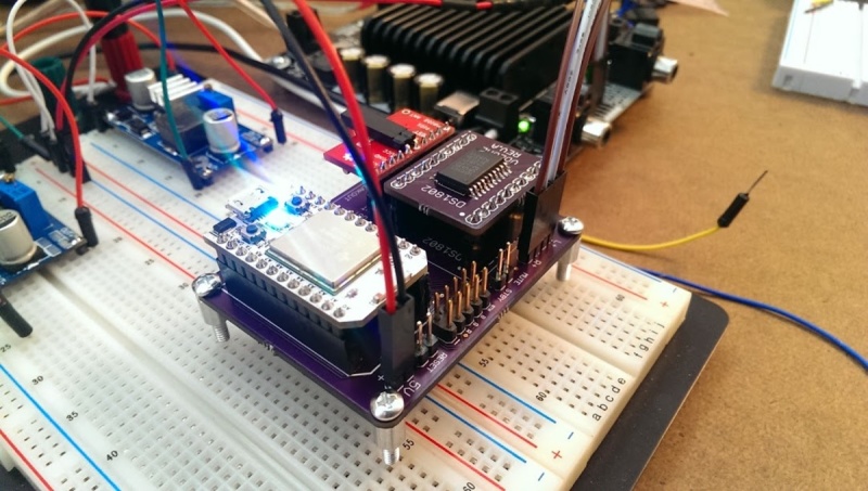
Your DS1802 is a good example of a part that has only digital +V supply but has a separate analog ground that you have to eventually tie to the same voltage as the digital ground, but should be filtered and routed separately.
Another thing I thought of after I wrote the previous post: you have two RF chips here, the Spark transceiver and the FM receiver so you could also be having radiated noise into the receiver. Can you run the system with Spark powered off after you setup the FM chip? That might help you figure it out.
I would use shielded cable for all the audio links between boards.
 (My plans are to put these in every room of the house)