Hello,
I know nothing about hardware, but I think I found an issue in your documentation.
It is said here Spark Docs | Examples that :
The positive (longer pin) of the LED is connected to D0 and its negative pin (shorter) is connected to ground via a resistor.
However, that is not what I understand in the picture beside the text:
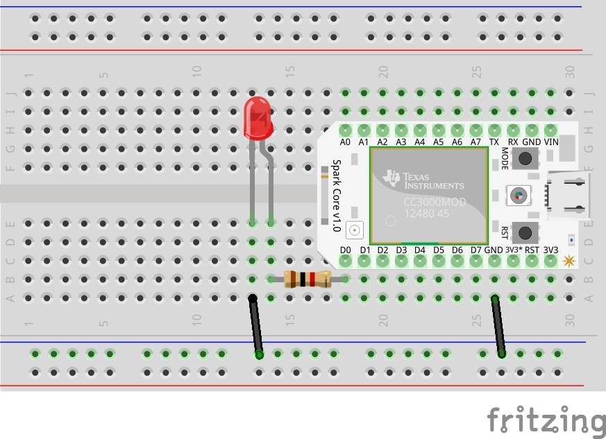
To me, the longer pin of the LED is the right one:
( )
| |
|
| |
[2] [3]
[2] shorter PIN
[3] longer PIN
Can you help me with understanding this example ?
I see that the longer PIN is connected to D0 via a resistor, and the shorter PIN is not connected with a resistor to the GROUND.
