Hi. I’m trying to use a Vernier temperature probe (found here) with a photon setup to take the temperature of some water. I used the data sheet for the sensor pins and this guide to set up my circuit (and my code). I know the code is good, but I can’t seem to get a good value when I analogRead the sensor pin. I keep getting 4092-4096.
Power supply (5v) -------(res = 15k)-----,-------(thermistor pin 5, res ~ 20k)-----ground(from pin 2)
analog pin A4 --------------------------------^
I’m not able to post a picture of my wiring setup, but this is a basic diagram of it. 5V supply goes through voltage divider with r1 = 15k and r2 = 20k. The voltage to pin A4 should be around 2.8V. I measured the lead to A4 with a voltmeter and get a reading of 5V. The probe is wired to a BTA connector to be able to interface with the photon. I’m not sure if I just have the probe interface wired wrong, or if there is something I’m misunderstanding about how the voltage divider should work in this situation. Please help.
You should not use 5V on the photon analog pins, they are only designed for 3.3V when used as ADC.
So anything over 3.3V will read as ~4096 and may damage the photon.
Since its a simple resistor device you can disconnect it from the photon and measure the resistance to know what you have to work with, it will vary with temperature.
Hi,
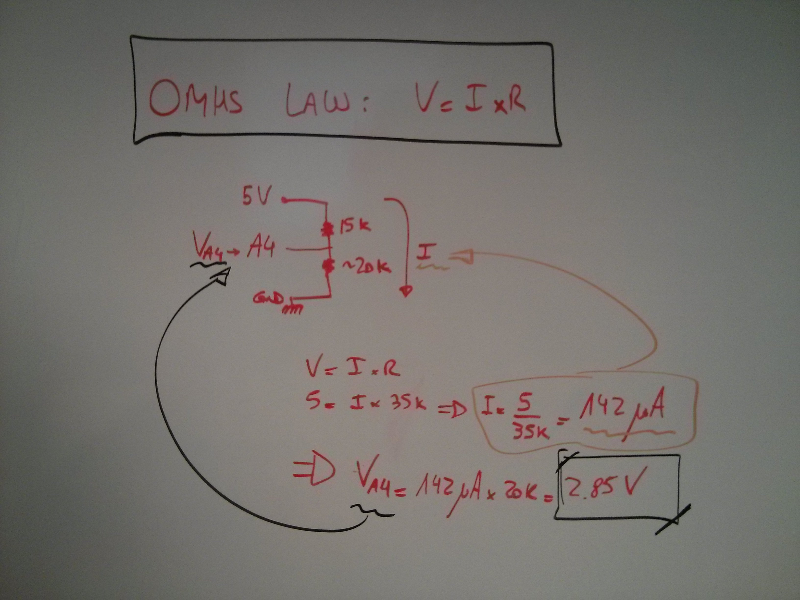
the voltage divider follows the omhs law.
This means that the maximum voltage in that A4 input will be around 2.85 volts, as long as you don’t change the 15k resistor. Even if the thermistor was replaced by a shortcircuit (a simple wire), voltage in A4 would go DOWN.
I would tend to think that the wiring is incorrect. Don’t leave it like that for too long, since as @MORA mentioned in the previous post, you could damage (if not already) the pin itself.
thank you for this opportunity to refresh the ohms law in my whiteboard!
Here is a pic on how I calculated the value:
This means that the maximum voltage in that A4 input will be around 2.85 volts, as long as you don't change the 15k resistor. Even if the thermistor was replaced by a shortcircuit (a simple wire), voltage in A4 would go DOWN.
But if it was replaced by a open circuit or the thermistor shows more than 20K resistance, due to fault or temperature, the voltage would go up.
@gusgonnet, voltage dividers are fine if you plan properly. In your case, you power the probe with 5V. If you switch to powering with 3.3V, the over-voltage risk disappears. You can use a buffering op-amp as well but I believe that complicates things for nothing in this case.
I see. So one would connect the voltage divider to the 3V3 output pin in the Particle to avoid an issue of over-voltage, as described by the OP.
great tip, thank you.
@rhafner6 : check if you can connect the probe to 3V3, instead of 5V, in order to protect your Particle from over-voltage.
EDIT: This may fix your issue, so try it out and let us know please
[quote=“gusgonnet, post:7, topic:19508”]
This won’t fix your issue though
[/quote] Not sure what you mean by this. The only consideration I did not include is the recalculation of the 15K resistor to the new voltage.
@peekay123, oh sorry, I was “talking” to the OP
He posted an issue about the voltage not being read properly in this thread, and then I diverged into the input protection.
thanks
I figured it out. I measured resistances between ground (pin 2) and the other pins on the probe’s bta connector. Pins 3 and 6 gave the correct resistance of around 26k and varied as I warmed the probe up. I tried doing the same thing when the probe was connected to the female bta connector that connected to the photon, but I got no values. I swapped out the connector and retested, this time getting the expected values. Reconnected everything to the circuit (with wires from pin 2 to ground and from pin 3 to the voltage divider as explained before) and reran my program and got more realistic values. It’s not quite right on the calibration as I’m getting ~ -18C for room temperature, but I just adjusted the equation to read -18 as ~20C and everything seems good.
Thanks for your suggestions and help, much appreciated.