So I got it all sorted out. I added .1µF caps between Vin/GND on both the high and low sides of the logic level converter and the 100µF cap on the power input to the Core. That cleaned thing up enough to be better, at least one of each 4 repetitions of the byte pattern was readable.
Then I realized the root cause and face-palmed … I have two diodes inline between the logic level converter low side pins and their connections to the D0/D1 inputs on the Core. These diodes have a .8V forward voltage drop. Meaning the 2.6V “high” is probably just barely enough to count as a 1 on the digital input.
The reason I put the diodes there is when the Core is powering on those pins go high and make LEDs on the AC control board light up. The diodes “Fixed” that problem but the signal coming out of the diodes is crap.
So one problem solved and other re-opened. I’ll start a new thread about how to make my logic level converter one way without the corresponding voltage drop.
Thanks again for all the help!
Schottky diodes have lower forward voltage drop.
But why is your Core powering those pins? Are they not only inputs in your project?
If you are facing an old foe that D pins are pulled low on startup, you might consider using A pins instead (but they are not 5V tolerant and not all can be used for interrupts).
1 Like
It must be that they are pulled low on startup. I’ll pick up some Schottky diodes to improve the circuit further but putting the diodes I have before the 5v to 3.3V level converter works, they do drop the 5V signal by around .8V as well but the level converter ensures the output levels are still 3.3V and I get nice consistent data.
Here is the “final” (albeit ugly) code: https://github.com/edalquist/ac_ir_control/blob/master/ac_status_reader/ac_status_reader.ino
Next step is to combine this with the IR control code I already have working.
2 Likes
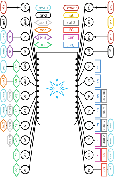
@ScruffR Is there an equivalent block diagram to the one you linked above for the photon?
This one doesn’t note the GPIO ports the pins are connected to: