I am attempting to create a particle powered set of parking lights. I would like it to be solar-powered so that it is self-sustaining, and for the lights themselves to be high powered LED’s. The general idea is that the solar panel would charge a battery by day (as well as powering the board itself), and at night the lights would
be activated by a mobile when needed. With this in mind, I have several questions related to this:
What sort of parts would be suitable and how would I construct the circuit that powers the board and charges the battery?
How would I go about powering and controlling the high powered LED’s?
Thank you very much for your help,
Will (aged 10)
Will, can you give a little more information? Are these parking lights on a car or in a parking lot? Are you wanting to turn them on with an app or just proximity to the device? What exactly is the use of the lights? IE: better to see your car at night in the parking lot or having a better visual indication of where your car is by turning them on?
What school are you attending? That project sounds abitious for a 10year old
I’d start a bench top setup with an Particle Electron (which already brings the charging logic and the battery connection with it), standard LED, a PIR sensor for motion detection, a photo resistor to tell when it’s getting dark and for the high power LEDs an n-channel MOSFET to switch the higher current needed for these LEDs - and of course some resistors, capacitors and other bits and bobs.
How many of these LEDs will you want to control and how long should the battery sustain them?
That influences the choice of battery and solar panel.
A Photon would be cheaper than an Electon, but then you’d need to add a solar charger and battery circuit like that
And in order to communicate with it wirelessly, you’d need WiFi coverage at the spot of your lights.
Your going to need to calculate the power draw of the high power LED lights in watts and at what voltage those lights will be running at, like 12v?
Once you know the power draw specs and how many hours per day you expect them to need to run then you can work backwards and figure out what size battery, solar panel, and solar charge controller you going to need to support that kind of load under real world conditions.
Do you need the Lights to come on based on a timer or do you want the lights to be controlled by some sort of remote switch? The Electron or Photon may not be needed for your needs.
There are solar charge controllers out there that have built in light timers and controllers which may be all you need if you just need the lights to come on at preset times.
I understood he'd want to use a mobile device (phone/tablet) to remote control the lights, so I'd "propose" a Particle device (over competitors ), but sure to cut budget, you may consider alternatives that don't come with this community
But if mobile stands for something like a vehicle then no radio enabled device would be needed at all.
To give some more information:
I am using a Photon, as the lights are close enough to be within wifi range. The intention is that the lights will be activated via an app on an iphone/ipad. I’d like the entire project to be solar powered, but am not quite sure how to do that. I talked to my Dad, and we thought maybe to use one of the phone solar chargers for the photon, but were not quite sure as to how to power the LEDs, given that they draw a high power. (here is a link to them http://www.maplin.co.uk/p/3w-high-power-white-led-n79jq). I made some rough sketches and a circuit, so here they are:
Don't mind the extra stuff on the left of the schematic, you'll only need this part
Depending on the LED you may need to add a current limiting resistor or it comes with its own circuitry for that.
Besides the output power question you may also need to consider what these chargers/powerbanks do when they don't see much current demand. Some just switch off after a while of "inactivity" preventing your device from waking from sleep. If you got such a charger already, just give it a try.
Also keeping the Photon awake a whole night might be stretch (in combination with the LEDs), since WiFi needs a fair amount of power - especially if weather situation doesn't give you a lot of recharge during day times.
You could consider a BLE enabled device like a Bluz or RedBear Duo. These are Particle compounds and have BLE support, which uses way less power and can be paired with iPhones.
As for the solar power, is that absolutely required, since it will complicate the project a bit? You’ve got 12W from the LED, and around 2W for the Photon (depending on operation). That’s 14W you need to power continuously. It then comes down to how big your batteries are, what kind of solar panel you’re planning on using, and perhaps more importantly, how long you plan on having the lights on.
If you could somehow wire it all into the mains network, you wouldn’t have to worry about power (conservation). Furthermore, should the mains power fail for whatever reason, then your router will probably go out too, disconnecting the Photon. You could connect to the Photon directly though that too would complicate matters further.
My suggestion is for you to try one of these 3w LED lights because they are not very bright at all. I’m not sure how much light your expecting or needing but it’s possible that 3w is not enough to satisfy you.
I build LED Lights in 3, 6, 15, and 27 watt ranges and anything under 15w is pretty weak.
The solar system will not need to be too large if you only need to power the lights for a hour or 2 per day.
As Scruff said a simple power FET will allow you to switch 12v power at higher currents with little trouble.
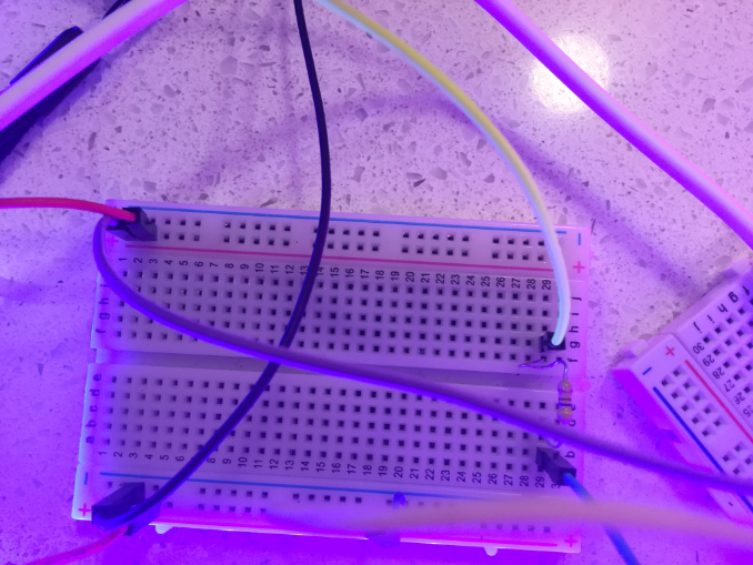
we made the circuit with a MOSFET and a battery pack which we will replace with a solar battery pack for some reason the LED’s on our test circuit were very dim! Could you check our circuit using the pictures below??
It’s a bit hard to tell how things are wired here.
e.g. you are using red jumper wires for + and - rails.
What exact FET are you using?
How many batteries does the battery pack have?
Try a 47Ohm resistor at the gate of your FET.
If you can supply a schema in addition to your photos and use unique colored jumper wires to tell them apart.
Do you know how to do the current calculations for your LEDs?
You seem to have no current limiting resistors there, which might eventually cause your LEDs to die.
You could plug your LEDs directly into the + rail (or - if you prefer) and the adjecent j column (a respectively) and the resistor across the e-f gap over to your opposite rail. That’ll look neater and saves on jumper wires
And maybe you can fit all components onto one breadboard too.
I have been working on this project this afternoon with my older brother and my Dad, we have found a different method. We are going to use USB power and a 5 volts power supply to power a LED strip, we will put a short strip in each of the four housings. Picture and link are below. We are waiting for the parts to arrive and we will let you know how we get on.
We have made great progress with our project. We have figured out how to make the LED strip work wirelessly through the particle. We are powering the strip via the particle 3V pin, and the whole thing is powered by solar rechargeable battery. Now we are moving on to the programming but we can’t tinker the digital pin yet. Does anybody have any advice on it?
That might be dangerous for the onboard regulator.
Too much current over that might make it burn out rather sooner than later.
The LED strip can be powered off the Vin pin (they are actually meant for 5V) and still be controlled via A2.
If I were you, I’d hook it up to the Vin pin, since the 3.3V goes through the regulator which may not like that much current draw. The neopixels are 5V to begin with, so that’s better anyhow. A filtering cap on the power supply wouldn’t be bad either.
For programming the animations, you’ll want to look at the library examples, and/or some projects on Hackster.
Thank you for that!! We are now using VIN for our power. Nothing has blown yet Thank you for saving us!
We’ll have a look at the particle function, but still a bit stuck on the code!
What we are looking for is a program that lets us A. have the strip all white B. be tinker able.
The code were finding is too complex for me (I’m still very new to this!)


 Thank you for saving us!