@faziban, can you tell me exactly which pins you have connected between the panel and your photon? How are you powering the photon and the panel?
1 Like
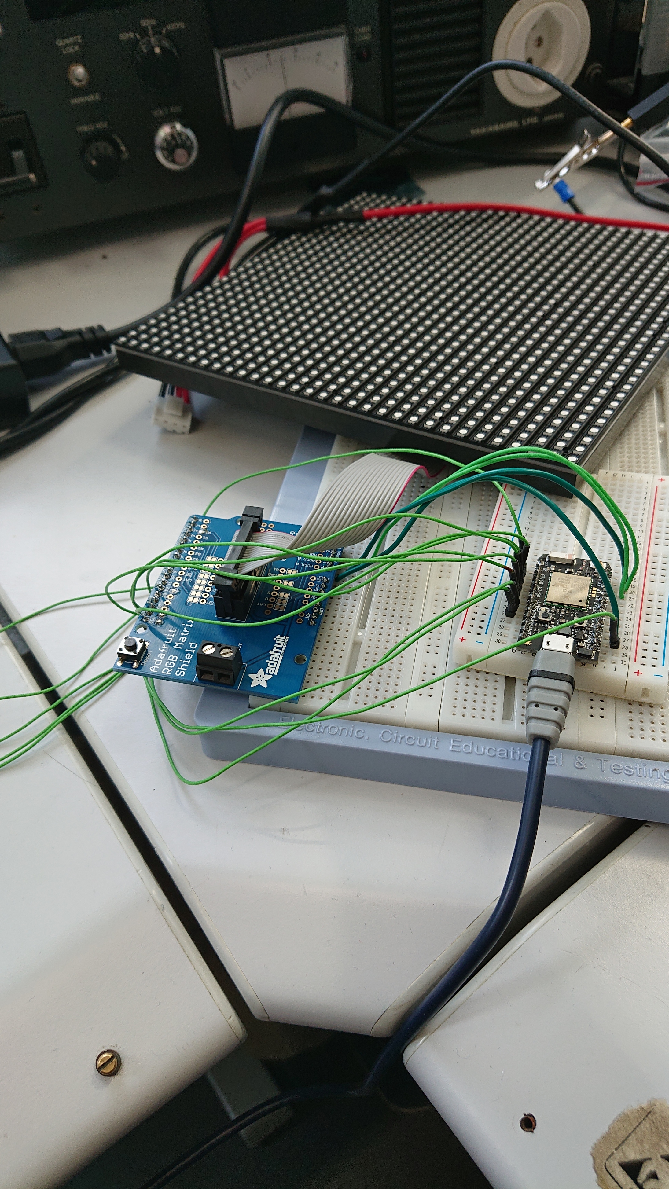
@peekay123 The Panel itsself is powered by an additional powersupply (5V 2A). The Photon is placed on a breadboard and very temporarely wired to an arduino shield, that saves the same purpose as your shield does (i suppose, i dont know for sure but i guess so (no offense taken please if im wrong)).
This is the shield https://www.adafruit.com/product/2601
And that would be the link to the Arduino Forum Thread where i first asked for help  and i didnt decide to use another Arduino, but swith to a more powerful platform: https://forum.arduino.cc/index.php?topic=604825.15
@faziban, I still need to know how you wired between the Photon and that shield. Also, I still need to know:
- How are you powering the Photon?
- Do you have the Photon GND connected to the shield GND?
A picture or two might be handy as well. 
1 Like

As i said the wiring is extremely temporary! 
But thts a good point, that the two grounds arent connected… ill do that!
And the micro USB Cable connected to the Photon is the power. 
btw the second picture is what the finished result should be… a word clock.
I like the Schwiizerdütsch wordclock 
2 Likes
@ScruffR haha thank you  i could give you the cad files if youre intressted in makeing one. the original, where i copied off the layout was berndütsch. im planing to laser the layout out of cerry wood panel
1 Like
@faziban, can you please give me a pin-for-pin connection list for the photon to shield wires you have.
@peekay123 These are my connections (out of the example file):
#if (RGBSHIELDVERSION == 4)		// Newest shield with SD socket onboard
	#warning "new shield"
	#define CLK	D6
	#define OE	D7
	#define LAT	TX
	#define A  	A0
	#define B  	A1
	#define C  	A2
	#define D	RX
And from the GitHub page of yours i found these comments:
@RickardPettersson, did you also wire up the RGB pins as indicated in RGBmatrixPanel.cpp:
#define R1 D0 // bit 2 = RED 1
#define G1 D1 // bit 3 = GREEN 1
#define B1 D2 // bit 4 = BLUE 1
#define R2 D3 // bit 5 = RED 2
#define G2 D4 // bit 6 = GREEN 2
#define B2 D5 // bit 7 = BLUE 2
@faziban, where does each of those Photon pins go to on the the Arduino Shield??
I do hope you're not powering the panel through the Photon, since that can consume several amps, which the Photon is not equipped to handle.
![]()
2 Likes
@peekay123 Sorry i dont 100% get your question :x
if (RGBSHIELDVERSION == 4)		// Newest shield with SD socket onboard
	#warning "new shield"
	#define CLK	D6
	#define OE	D7
	#define LAT	TX
	#define A  	A0
	#define B  	A1
	#define C  	A2
	#define D	RX
so the D6 Pin on the Photon is connected to the Clock Pin on the Arduino Shield and so on.

The connections on the Arduino Shield are like on the picture above.
I dont have the whole setup next to me right now, but i could try to describe it bettwer tomorrow.
1 Like
Here is the Pin to Pin Connection.
Photon:					ArduinoShield
TX						digitalIO 10 (LAT)
RX						analogIn 0 (ADDR A)
A0						analogIn 1 (ADDR B)
A1						analogIn 2 (ADDR C)
A2						analogIn 3 (ADDR D)
D0						digitalIO 2 (R1)
D1						digitalIO 3 (G1)
D2						digitalIO 4 (B1)
D3						digitalIO 5 (R2)
D4						digitalIO 6 (G2)
D5						digitalIO 7 (B2)
D6						digitalIO 8 (CLK)
D7						digitalIO 9 (!OE)
The definitions in the brackets are the ones which are reffered to in the code and on the Arduino shield.
I hope that helps further. If not, i culd try to make a visio sheet to visualise it better.
@faziban, not sure you have the connections quite right:
Photon:		ArduinoShield			Change to
TX			digitalIO 10 (LAT)
RX			analogIn 0 (ADDR A)		analogIn 3 (ADDR D)
A0			analogIn 1 (ADDR B)		analogIn 0 (ADDR A)
A1			analogIn 2 (ADDR C)		analogIn 1 (ADDR B)
A2			analogIn 3 (ADDR D)		analogIn 2 (ADDR C)
D0			digitalIO 2 (R1)
D1			digitalIO 3 (G1)
D2			digitalIO 4 (B1)
D3			digitalIO 5 (R2)
D4			digitalIO 6 (G2)
D5			digitalIO 7 (B2)
D6			digitalIO 8 (CLK)
D7			digitalIO 9 (!OE)
ALSO: Make sure the panel power GND connects to the shield GND and to the Photon GND. All three grounds must be common.
1 Like
@peekay123 Thank you very much, ill try that tomorrow and tell you how and if it worked as expected!
Yeah, i completely forgot to connect all the GNDs.
1 Like
@peekay123 I have just tried it out and it does something, but not what i was expecting And also not what i want it to do, not what its supposed to do…

As seen in the picture above, some lines keep flashing up and flickering.
Its doing something, so i dont expect the code to be corrupt or faulty.
I rather think that i did another error wiring this thing.
Any ideas what to try next?
Double check the wiring I'd say?
I agree with @Moors7. Also, which version of the library are you using compiled for which DeviceOS version? I have not recently tested the RGBMatrixPanel with the latest DeviceOS. However, protoboards can be finicky and your jumpers look homemade. Where is the common GND between the panel, the shield and the Photon? Ideally, you are not using the GND from the ribbon cable.
Personally, I would used the shield screw terminals and connect the panel power there and then power the photon from the 5v pin on the shield to the Vin pin of the Photon (no USB connected). Nonethless, your setup should work.
I just checked the wiring 3 more times and it seems correct or i need glasses. :x
@peekay123 ill try that with the power from only one source after my holidays, which are next week.
Until now that you everyone very much for all the help last couple of days! Ill be back at the grind in one week Have a good time till then
1 Like