Particle leds blinking crazy and overheat

Hello guys!
I made a mistake and gave the photon a wrong command, like digitaloutput a certain voltage
After flashing the code, it went down (no leds active)
I disconnected the usb and reconnected, then both green/red lights are blinking crazy, as well blue led. All the three blink really fast and the photon runes super hot

Tried to reconnect to usb, not recognized (not seen by pc)
Tried to manually factory reset, but i cannot enter any mode (nor DFU nor factory reset)

And it is super hot near setup button when i connect usb

Any idea how to solve?

Code alone can’t overheat, nor damage your device. You can’t make it output more voltage than it’s capable of, so my best guess it that something in your external circuit was off and caused issues.

A video of the device would be nice, since ‘crazy colors’ and “red, green, and blue” doesn’t say much.

Furthermore, there is no factory reset on the photon, so it’s not surprising you can’t execute that


1 Like

Actually it should have, in the datasheet of the wifi photon board it says you can factory reset by holding setup+reset

By the way it was connect to an l293d, which was driving 2 dc motors. All was fine, when i tried to give as output “analogWrite(pinX, map(60, 0,100,0,255))” in the setup options (when i come back i post the code and the video).after i pressed upload code, the photon went off after a certain amount of seconds. No one led was blinking anymore.

I have tried disconnecting all, but i can’t enter any status to flash code

Before i manage to post a video (when i come back home) i try to describe the error:
Central led has 2 light right? Green or red. Moreover u have blue light on d7 pin. These 3 light are blinking simultaneously together, without interrupting, setup button goes really hot and after a while the red&green lights in the middle start fading.

I have tried to cooldown the area around the setup button and it seems that when i breath above it the green&red lights start again to flash, but when i end up the breath, they go off again. It is like there is some component overheating (and when you touch the area u actually feel it is really hot)

This happens even if i remove the photon from the breadboard

As @Moors7 said, there is no factory reset for the Photon, so you should explain exactly where in the data sheet you saw this, because if you were looking at the correct data sheet, then there is an error in the docs that should be fixed.

I wonder if you tried to draw to much power from the Photon that may have damaged the voltage regulator. How were you supplying power (both Vcc1 and Vcc2) to the L293D chip, and what motors did you have connected?

I saw from the page that talks about the wifi module, i will post later.
But if it has not is ok. I want to figure out a way to reset him or put in dfu, if it exists
For power: Vin of photon (it should have 5v output, right? Because i use USB to charge the photon so vin becomes an output) goes into the vcc1 and 2 of the l293d. Then from d0 and d1 of the photon, i give an analogwrite to give current to “enable 1” and “enable 2” of the l293d
(Btw, i am on my way home and will post the config)

When used as an output, Vin is only capable of supplying 1A max, and depending on what motors you were using, you may have exceeded that. I think the way you should use that chip is to power the chip itself (Vcc1) from the Photon, but hook up a beefier power supply to Vcc2 that’s used to power the motors.

Voltage is not the only thing power is made of - as @Ric already said the current is important too.
And when dealing with coils (like a motor or relay) you also need to consider flyback effects of the collapsing magnetic field.

With your description I’d say you’ve blown the on board regulator and there is no way to reset the device as it’s damaged hardware which needs to be replaced.

BTW, even an analogWrite(pin, 54686316) won’t damage the pin as these functions only accept valid values.
But with an H-bridge you can go wrong when applying disallowed combinations that short circuit two pins as shown here

Here it the code i used. The bold part is the addiction

Btw i used the whole thing all the afternoon, playing around it. Had no problems with. How could it happen all of sudden?

// --------------------------------------------------------------------------- Motors
 int motor_left[] = {A5, A4};
 int motor_right[] = {D4, D5};
 int leftSpeedPin = D1;
 int rightSpeedPin = D0;
 int motorSpeed=0;
// --------------------------------------------------------------------------- Setup
void setup() {
Serial.begin(9600);

// Setup motors
int i;
for(i = 0; i < 2; i++){
pinMode(motor_left[i], OUTPUT);
pinMode(motor_right[i], OUTPUT);
}
pinMode(leftSpeedPin, OUTPUT);
pinMode(rightSpeedPin, OUTPUT);
Particle.function("forward",driveForward);
Particle.function("stop",motorStop);
Particle.function("right",driveRight);
Particle.function("left",driveLeft);
Particle.function("back",driveBackward);
Particle.function("speed", setSpeed);
setSpeed("60"); // <-- addition
}

void loop() { 


}


int setSpeed(String mov)
{   int velocit =0;
    velocit = mov.toInt();
    int motorValue = map(velocit, 0, 100, 0, 255);
    analogWrite(leftSpeedPin, motorValue);
    analogWrite(rightSpeedPin, motorValue);
    return 0;

}

int motorStop(String movimento){
digitalWrite(motor_left[0], LOW); 
digitalWrite(motor_left[1], LOW); 

digitalWrite(motor_right[0], LOW); 
digitalWrite(motor_right[1], LOW);
delay(25);
return 0;
}

int driveForward(String movimento)
{
digitalWrite(motor_left[0], HIGH); 
digitalWrite(motor_left[1], LOW); 

digitalWrite(motor_right[0], HIGH); 
digitalWrite(motor_right[1], LOW); 

return 0;
}

int driveBackward(String movimento){
digitalWrite(motor_left[0], LOW); 
digitalWrite(motor_left[1], HIGH); 

digitalWrite(motor_right[0], LOW); 
digitalWrite(motor_right[1], HIGH);
return 0;
}

int driveRight(String movimento){
digitalWrite(motor_left[0], LOW); 
digitalWrite(motor_left[1], HIGH); 

digitalWrite(motor_right[0], HIGH); 
digitalWrite(motor_right[1], LOW);
return 0;
}

int driveLeft( String Movimento){
digitalWrite(motor_left[0], HIGH); 
digitalWrite(motor_left[1], LOW); 

digitalWrite(motor_right[0], LOW); 
digitalWrite(motor_right[1], HIGH); 
return 0;
}

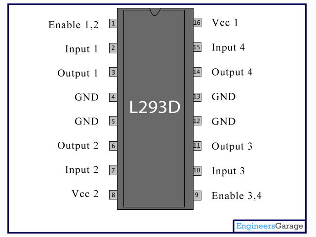
And instead this is the config, exept that i had no battery pack but direct link from my Photon to the Vcc1 and Vcc2 of the l293d

It could be that you were operating too close to the limit of power that the Photon's regulator could supply, and that you eventually fried it. It would help to know what motors you were using. Do you have a link to those?

@Ric, the Photon’s diode can actually handle a max of 3amps though I wouldn’t push it that far.

Diode? Are you referring to the diode connected to the USB power input? Actually, as I think about this some more, I don’t know why he might have damaged the regulator (the symptoms would suggest that), since where he might be drawing too much power from is Vin. I’m not sure how that would affect the Photon. Depending on where he’s getting his USB power from, I would think that Vin couldn’t supply more than 1A; if you try to draw more than that, would that cause a voltage drop to the input of the regulator, and could that damage it (related to the problem we’ve seen with low battery voltage damaging the regulator)?

MOTORS:
Como Drills DC Motor part 951D10216V

And actually, A4,A5 and D4,D5 are connected to the input ports of the L293D
D0,D1 of photon are connected to enablers of L293D (to provide PWM)
Outputs of L293D are connected to motors.

So the configuration in the photo that I posted would be ok with a photon? How should I modify it in order to work properly? (Because if I use Vin to feed the photon, then I can only use the 3v3 output to provide voltage and current to L293D, instead from arduino I see that 5 volts are fed as the min voltage in L293D. Will it be a problem if I send to L293D Vcc1 my photon 3v3 voltage and to L293D Vcc2 my battery pack 9V?)

The regulator can be damaged in multiple ways. One of which is noise on the supply rail. And since motors are some of the worst sources for that prolonged use with poor filtering can push the regulator over the edge (sooner or later).
That's also why saying: "But it worked so long!", is no proof that a particular setup was fine.

Nope, you can feed into Vin and to the H-bridge from the same source, but you need filtering and stay within the limits for Vin.


What i mean is that Vcc1 should be fed from the particle (so from 5v or 3v) and Vcc2 should be the one from the battery, right?

How can i setup the whole schematics with a battery pack of 4xAAA (so i guess 9v)? I should use some resistance between the battery and the Vin of the Particle i guess, to reduce voltage in the range of 5v

The L293D needs a minimum of 4.5V on Vcc1.
4xAAA = 4x 1.5V = 6V (when using alkalines)

But if you had 9V a series resistor would not be what you want to reduce the voltage for Vin.
You should rather use a regulator or buck converter for that.

Ok, so 4xbatteries should be enough to feed both Vcc of L293D and the Particle, right?
Do i have any issue if i feed Vcc1 and Vcc2 wih the same voltage/current (both from batteries)?

As said earlier:

That applies to Vcc1 & Vcc2, but if you want more power for the motors you can seperate Vcc2

And what you mean by filtering?
How you would setup the thing?
Sorry for the questions but i am a total beginner

Andrea

I'd add some caps (e.g. 47-100”F + 10-100nF) near Vin and maybe near the Vcc pins too.

Ok thanks for the reply!
I will try to assemble it and test it as soon as my new particle is here :cry: