when I see words like coupling of RF noise and impedance I get cold sweats
Noise gives everyone cold sweats, so you aren't alone!
Yes, the 0.1uF is a decoupling cap. Often an app note will recommend the value but I don't see one in the datasheet. It should be on the nRF CE pin side.
The uC pin should never be an input when you use it to drive the CE pin. That's pretty confusing to me.
Usually either a pull-up OR a decoupling cap on one pin. The pull-up stabilizes your HIGH supply so that the uC output pin doesn't have to send all of the energy. With a pull-up, you allow power to come from the supply and the pin just shunts to GND when you send it LOW, make sure the pull-up resistor is large enough that you don't shunt too much power (check datasheets). This fixes a situation where your pin lacks the power to drive the line, it does nothing for noise.
If the supply is noisy, like @Backpacker87 suggests, then it's not more power, it's a clean signal you need. The cap smooths the voltage, like a damper in a car's suspension, so that it doesn't bounce around. If you use them together you start to filter specific frequencies, a wire plus a cap is just a very low value resistor and a cap so it's works the same but you aren't building a filter so the resistor shouldn't go in-line.
The cap from Vcc to GND is why this sounds predictable:
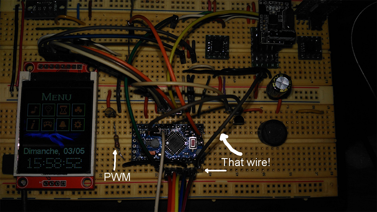
As a last, last note, I can use a PA model powered with only two coin cells in series with a 3.3V linear regulator and a 33uF cap on the NRF’s power pins and it’s working without a single problem.
The 33uF is a decoupling cap that's filtering noise on the power supply. Why a 0.1uF cap kills your TX when attached to CE is confusing, but the cap causes a dampening, remember, so if you don't allow enough time for the CE voltage to rise from 0 to 3.3V it will never get high enough and before you shut it off. On the CE pin it has to be a lower value, but if you tie the CE pin to Vdd with a pull-up resistor and then put a 33uF cap between Vdd and GND very near to the resistor connection I wonder what will happen?
I think that might look like this sketch if you use a 22uF cap decoupling Vdd, and a 10k pull-up on CE, but check my connections before you trust this and adjust the values as necessary. Maybe @Backpacker87 could comment as he has experience with this IC:


