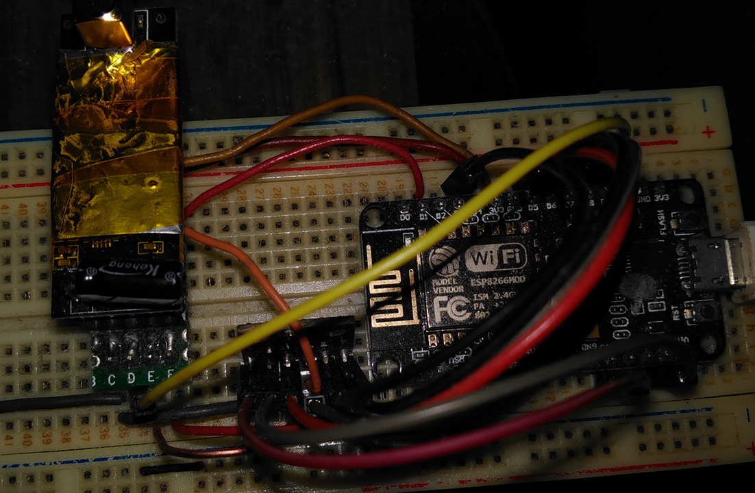
@Backpacker87 That’s the PA/LNA model I’m using. In the picture it’s replaced with a pcb antenna model so I can work. I just wanted to show (brag!) that I use them a lot. To move on from the frustration I will not try to fix the problem anymore.  I did put a bit of foil around them using cling wrap first, and I tried removing it too. That’s one of the ‘hidden’ with the foil (and my first remote I keep by the window for when I smoke a cig). NodeMCU + NRF with the NRF powered by the NodeMCU 3.3V. No problem there. The MP3 player is even worse since it’s buried in a sea of cables and wires and still no problem. So I’m done investigating. I will try the power module out of curiosity but for the rest, I will work with a non-PA/LNA model on that breadboard. Everything else is working too well to insist on finding a solution.
I’ve just run into the same problem using a ProMini, nRF24 and E-ink display. Pullups, pulldowns and capacitors didn’t work, but once I touched the CE pin on the ProMini with my finger or a DMM lead, the receiver would start working and continue to do so without my finger until I cycled the power. In the sketch I’d used the default 7 and 8 pins for CE, CSN respectively. But if I changed to use pins 5 and 6 instead the problem went away. No theories as to why that is, but it’s worked for me.
Hi Guys,
I have the same problem. But since I am hardware engineer, I have more infos but also no solution because I do not have an oscilloscope for 2.4GHz. It is not the CE pin!!! If you move your finger 1-2 mm close to the antenna without touching it, it also starts sending. The same you can do with your finge above the PCB 1-2mm but not touching it, it starts sending. So, this hase something to do with grounding or a suboptimal connection to the SMA antenna (reflections). A small capacitive load through air changes the behaviour. Then, I placed a 1mm metal plate below the antenna (again not touching the antenna), no finger of the metal plate, metal plate is isolated (no ground). Module starts sending. It is definitely an antenna coupling problem or a bad ground of the PA!
Harald
Some more info:
I have decoupling capacitors very close to VDD and GND, one 10µF/25V X7R (low ESR) and one 100nF X7R. In some posts, I have read that putting an 8.2pF also in parallel to those 2 increases the transmission range (distance) by a factor 2-5. Have not yet tried it, because the wire distance from PA to the connector and from there to my decoupling caps is far too long that such high frequencies filtered by 8.2pF will pass through (the longer the wire/PCB track, the higher is the impendance, especially at 2.4GHz).
And I have found one more interessting thing:
I have several modules with PA and SMA antenna (sorry for the mistyping before!). There is a diference on the modules which are working without finger and with finger only.
If you have the module in front of you, SMA antenna to the right, 8 pin connector on the left. The left square chip is the nRF24L01+, the right square chip is the PA. Below the PA (closer to you) are 2 capacitors (Version A) or 3 capacitors (Version B). Version A is always (!!!) working without finger, all (!!!) Version B are working only with finger!
I must find out what these capacitors are doing, but it is a min. 4 Layer PCB with the tracks in the middle layers. Not so easy. I’ll put the modules under the microscope, hope I can read the values (seems to be 0805 or 0603 size). My eyes are not very good.
@Harald, welcome to the forum. Nice work, I’m interested to see your findings.
Mave looked onto the PCBs more in detail, these are not capacitors but resistors, so on Version A modules 2 resistors and on Version B modues 3 resistors.
Version A:
PA is RFAXIS X2401C AB1246
Resistors are both 102, so 1KOhms
Version B:
PA is RFAXIS X2402C AB1210
Resistors from left to right:
102 (1KOhms) 102 (1KOhms) 103 (10KOhms)
Harald
Hi Backpacker87
have not seen your response earlier because I was typing. Greetings back to you and all others here.
Harald
Have downloaded both datasheets (X2401C and X2401C). The 10K0 resistor is connected to a pin DET on X2402C which is an analog output proportional to the TX power. Did not yet find any details about it, only that it should be connected to GND via 10KOhms and goest to the transceiver. This pin was NC (not connected) on X2401C. The other 2 resistors (1K0) are also o.k. and are series resistors to the TXEN(able) and RXEN(able) pins of the transceiver chip. Try to find out more about the DET pin. But if it is a crosstalk from other tracks (especially the tracks to the antenna) or a bad layout (impedance/coupling 50Ohms) tot he antenna, I believe that I can not find it and must purchase othere modules from a different supplier and then hope the best.
Harald
Have taken a look, thank you. The PCB antenna version can not be used in my project, I need the version with antenna. I also looked at the site (https://www.nicerf.com/). They are in Bao An (Shen Zhen). I have worked there long time and I can ask our engineer in China (Dong Guan) to buy them. With approvals, it is much better. Up to now, I have never had problems with my current modules, I have a lot of them (50+). Only the last 10 pcs sent by our engineer there have the problem. I did not yet find the reason. Today, I unfortunately have no time. Tomorrow, I continue on that problem. Sorry for the late response, I am in Germany and stopped working after writing my last comment.
I am getting closer to a solution:
Touching (or nearby without touching it) the antenna may have 2 consequences: The signal may get better, my finger works like an antenna, or (higher probability) signal may get worse, my finger is shielding the RF signal. To check consequence 2, I changed the code for the TX Power:
Command 0x26 is write command to register 0x06:
NRFCmdData(ucModule,0x26, 0x06); //TX Mode, sending at 1MBps at 0dBm
//-----xx- ‘00’ : -18dBm 0x00
//-----xx- ‘01’ : -12dBm 0x02
//-----xx- ‘10’ : -6dBm 0x04
//-----xx- ‘11’ : 0dBm 0x06
Sending at max. Power (0dBm) did work on my module 1 (2 resistors, X2401C) but only sometimes on my module 2 (3 resistors, X2402C). Then changed to less power, with -6dBm 0x04 it became better, with -12dBm 0x02 all packets transmitted without a single packet lost!
My finger is a kind of shield or better an attenuator, reducing the output power and therefore also possible reflections. Maybe, the X2402C can output much higher power than the X2401C. So, reducing its input power also should reduce the output power.
Either the output power of the nRF24L01+ is too high for the input of the X2402C (low probability) or the output power is too high for my receivers to decode the signal (overdriven)(could be checked by increasing the distance) or the high output of the X2402C causes reflections in the antenna path (highest probability).
Give that a try! It seems logical to me.
But I will do more tests, because reducing the output power should also decrease tranmission distance. But I already have an idea: I have 100s of transceivers in the room with small nRF24L01+ modules with PCB antenna and one single central unit with the nRF24L01+ modules with PA and SMA antenna. My central can send packets to my 100 transceivers and they respond (or not) and the central can try values 0x06 for the ones far aways and 0x04 for nearby units and 0x02 for very close units.
This even can be done if the units are moving around like in my case. A higher protocol layer can adjst the output power dynamically.
Since all my units are 100% synchronous (+/-1 microsecond), I even can transmit 0x06,0x04,0x02 packets one after each other (every 500usec one packet). If my central would like to talk to a specific unit, it already knows at which power to send.
Harald
My solution to the problem was connecting the IRQ pin of NRF to an empty port in Arduino, D7 port to be precise. It isn’t used in the code and was floating previously as many instructions on the web tell to just leave it hanging. Also an interesting fact regarding the noise, none of the touching of Arduino didn’t help at all, the issue was fixed after touching the NRF. Also the noise was so significant that it event caused to affect Arduino’s serial output which was screwed from time to time. After connecting the IRQ pin the issue resolved…
There was something other wrong. The only reason why connecting the IRQ pin to a default input pin of the arduino should solve a problem can be, that most of todays MCUs have so called weak pull-ups internally of every pin to avoid floating, because floating pins draw supply current and therfore may inject noise. I never leave pins open in my designs. I checked the nRF24L01+ datasheet and the IRQ pin is an active output push-pull pin (no an open drain which must be pulled up externally).
But what I have described here is not a problem of noise, it is definitely a result of the selected output power. And I already have built-in the above described method to adjust the output power automatically.
And from an electrical view this also is clear and simple:
The nRF24L01+ with power amplifier behind can reach a free air distance of 1000m with SMA antenna (not the PCB antenna). So if my receiver is 1-10 meters away, it is definitly overdiven as described.
If I reduce the output power, the packet transfer quality increases dramatically in that case.
With full output power and a distance of 1-2 meters, one packet per 3-5 packets is lost (the CRC is bad). At 10 meters distance, 30 packets per 500 are lost. In the moment I reduce the output power (nobody can touch anything, because my comlete electronic is in a case) by a PC command via USB to the MCU to the nRF24L01+, the quality at 10 meters changes to 2-3 packets lost of 500.
And at 1-2 meters distance I can only receive packets if I remove the SMA antenna!
It is definitely the output power.
In my design I use the IRQ naturally because polling the status register is sub-optimal.
One further idea: Maybe you do not have original Nordic chips. There exist boards with nRF24 printed on it but internally there is a different die. Have seen pictures of those dies. And maybe the chinese “compatibles” have an open drain output so that several of them can share the same IRQ input pin of the MCU. Those open drain pins may inject noise if no external pull-up is connected. I place any bet, that if you remove the IRQ from D7 and instead solder a 10K0 or 4K7 pull-up to the IRQ pin, the problem is also gone. And the reason for noise in most cases is a bad GND connection. Also the external 10µf between VDD and GND should be a low ESR type (e.g. X7R).
Harald
Encountered With The Same Problem Changing The Default 2dB Antenna To 10dB Resolved My Problem.
Im Using NRF24L01+ Module