I made a device using Photon where I read the status of AC line using optocoupler.
If there is no AC power in the line then optocoupler (LTV-814) gives 0 otherwise 1.
I used extenal Pull Down resistor with optocoupler.
Problem:
Optocoupler is working perfectly and it gives proper reading when tested using multi-meter but
‘status’ variable in program strangely give wrong output sometimes when I check on console.
I.e. status’ digitalRead() reading after 4-5 times, gives 0 while it is 1 in actual.
Suppose optocoupler from 1 to 3 are HIGH and status shows 11222 but when I check more times then sometimes it gives 11111 in-between while optocoupler from 1 to 3 are still HIGH.
I set as INPUT, INPUT_PULLUP, INPUT_PULLDOWN but still problem is same.
Please help me.
I am struggling from last 2 days and totally exhausted. # I tested with several Photon devices also.
Program Code:
//SYSTEM_THREAD(ENABLED);
int statusPin[5] = { A0, A1, A2, A4, A5};
int status;
int statusRead[5] = {0, 0, 0, 0, 0};

void setup() {

   //INPUT Pins
  for (int j=0; j<5; j++)
    {
    pinMode(statusPin[j], INPUT);
    }

    Particle.variable("status", status);
}
void loop() {
    statusCheck();
}

int statusCheck()
{
    for (int s=0; s < 5; s++)
    {
        statusRead[s] = digitalRead(statusPin[s])+1;
//Here, I add +1 in digitalRead to make proper number like 11122,
//1 means OFF (Optocoupler reading is 0) & 2 means ON (reading is 1)
    }
    status = statusRead[4]*10000 + statusRead[3]*1000 + statusRead[2]*100 + statusRead[1]*10 + statusRead[0]*1;

    return status;

// I also tested by putting this function code directly in loop also
}
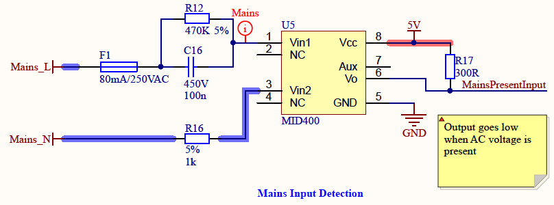
Possible reason with your optocoupler reading working with a meter but not with a digital read is the impedance of the Photon is not high enough. You could try using a unity gain buffer IC or a GPIO expander. In one of the boards I have I use a MID400 IC to detect the presence of AC mains supply. The output signal goes to a GPIO IC and this works. I have included the circuit schematic below. F1 may not be necessary for you, R12/C16 provides the correct resistance to the flow of AC current through MID400.
One observation on your code; have you tried slowing down the calling of statusCheck() in the the loop()? As it stands the loop will be running at 5-10K/s - maybe a short delay(200); or call it from a timer.
In past, I used this optocoupler with other MCU and worked perfectly.
Such kind of reading by digitalRead() work most of the time in Photon also but when I fetch the status again n again due to need of application then it shows 11111 in between then after 8-10 times correct reeading, it again shows 11111 and so on.
Rest time, it shows correct reading like 11222
Actually, I have to go with LTV-814 due to several reasons.
So, please any kind of help/suggestion by keeping this optocoupler in mind.
Do you really think, optocoupler output will be weak enough so that Photon’ digitalRead() might miss the reading and can show wrong value?
Why most of the times, Photon shows correct reading if its impedance is not high enough?
I also slow down the statusCheck() by keep in condition if stateChange of optocoupler then
fetch the status.
Note: I installed the switches also in AC line to simplifying the testing. I can easily turn OFF or ON the AC line.
When I turn ON the AC line, optocoupler gives 1 reading and Photon also shows the same.
But when I multiple times fetch the value of ‘status’ then Photon shows 0 sometimes but in actual, AC line is ON & optocoupler is giving correct reading.
statusCheck keep in condition also to slow down the loop() effect on ‘status’ variable and use AC switches for state change
Like this:
void loop()
{

    for (int s=0; s < 5; s++)
    {
    currState[s] = digitalRead(statusPin[s]);
//currState[] & prevState[] initialized in above of the program.

   if (currState[s] != prevState[s])
    {
    status = (digitalRead(statusPin[4])+1)*10000+(digitalRead(statusPin[3])+1)*1000+(digitalRead(statusPin[2])+1)*100+(digitalRead(statusPin[1])+1)*10+(digitalRead(statusPin[0])+1)*1;
    prevState[s] = currState[s];
    }
    }
}
LED on the Photon is cyan i.e. online during running this.
There is no red led or such error indicated led not blinked in whole process.
int statusPin[2] = { A0, A1};
int status;
int statusRead[2] = {0, 0};

void setup() {
    Serial.begin();
   //INPUT Pins
  for (int j=0; j<3; j++)
    {
    pinMode(statusPin[j], INPUT_PULLDOWN); //Used INPUT, INPUT_PULLUP also but problem is same
    }

    Particle.variable("status", status);
}
void loop() {
    statusCheck();
    delay(1000); // Serial output in every 1 second
}

int statusCheck()
{
    for (int s=0; s < 3; s++)
    {
        statusRead[s] = digitalRead(statusPin[s])+1;
    }

    //statusRead[4]*10000 + statusRead[3]*1000 + statusRead[2]*100 +
    status = statusRead[1]*10 + statusRead[0]*1;
    Serial.printlnf("Status:%d", status);

    return status;
}
Output in serial:
//To make it simple, reading two pins (A0 & A1) only
//Here, 22 means both optocoupler detects AC and produced HIGH signal.
// I added +1 in digitalRead() that you can see in program i.e. 2 means HIGH
Status:22
Status:22
Status:22
Status:22
Status:22
Status:11 //See after 5 to 7 seconds, it shows 11
Status:22
Status:22
Status:22
Status:22
Status:22
Status:11 //After 5sec
Status:22
Status:22
Status:22
Status:22
Status:22
Status:11 //After 5sec
Status:22
Status:22
Status:22
Status:22
Status:22 //generally after 5 to 7 seconds such output come
For one, that should be for (int j=0; j<2; j++) (same for your s loop) - with a zero-based statusPin[2] and statusRead[2] your indices range is 0 and 1. 2 is disallowed, but with your check for j<3 you will inevitable also access this uninitialised field and setting statusRead[2] may actually be corrupt some other memory cell your program relies on.
When you intend to probe an AC signal, you should probably sync your code to the frequency of your signal. A delay(1000) will not do that.
Yes, I rewrite the program as lite program.Due to this, I forget to edit the j<3. I corrected when I run the program here.
Well, problem of output reading is still there.
When you intend to probe an AC signal, you should probably sync your code to the frequency of your signal. A delay(1000) will not do that
From optocoupler datasheet, I used the same circuit (as above) and optocoupler gives high signal in output if there is AC power input.
So, there is no such sync is mentioned I searched on google and other platforms as well.
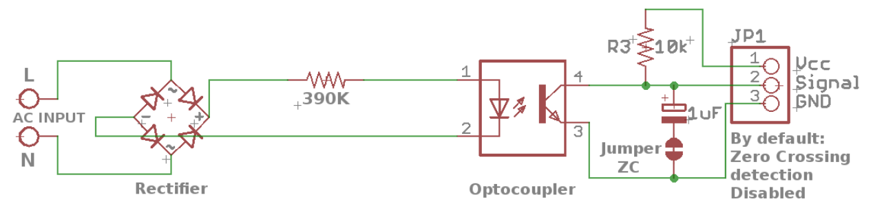
Given the LTV814 works with current in either direction - perhaps you should try adding a 1uF or 2uF capacitor and pulling the signal up to VCC as per this schematic.
Yes, that might be the case when the actual AC level exceeds the forward voltage of the LEDs there will be times where the signal just not and during that periode (around the zero-crossing mentioned by @armor) both LEDs will be off and hence the transistor not opened.
The RC combo in @armor's schematic should close that gap in the signal.
Thank you so much @armor and @ScruffR
You are correct that adding capacitor might solve the problem.
I connected 100uF capacitor between VCC & Signal because I have only 100uF available right now and why between VCC - Signal: because I used pull down resistor in output.
After that, it shows correct reading.
// I tested for 3 optocoupler and Left side digit tells the signal of optocoupler 3,
// which is connected with 100uF cap.
Status:222
Status:222
Status:222
Status:222
Status:222
Status:222
Status:222
Status:222
Status:222
Status:222
Status:222
Status:222
Status:222
Status:222
Status:222
Status:212
Status:211 //1st and 2nd place goes to 1 while 3rd is still 2 (ON)
Status:211
Status:211
Status:212
Status:222
Status:222
Status:222
Status:222
Status:222
Status:222
Status:222
Status:222
Status:211
Status:211