I am very new to the Photon coming over from Arduino. I am making a RFID scan in system for a project to replace a current system. The RFID integration was super easy and I love the simplicity, the integration of the LCD is not going so well.
I have this LCD display:
Using the LiquidCrystal library and the example project following their pin layout (no i2c chip) and I am not able to get it up and running. They ONLY change I have made is to set the screen size to a 20x4 vs. a 16x2. Even leaving the 16x2 doesn’t work. Screen is lighting up and 10k pot is working just fine… but only first and 3rd line are showing character placement (just boxes).
I’ve been scouring the internet trying to find an example to get this working with no luck. Any thoughts?
Thank you for the reply. I am going to try a Shield Shield for my project to bump the LCD up to the 5v that I need. Seems like a good option.
I am unfamiliar with only 4 data inputs… this would be nice to make work to save some space on the board since I have the RFID and a buzzer for when the card is scanned. I actually didn’t know this was possible.
Thanks for the tip on slowing down the LCD calls. I’ll test that out as well.
I am going to mess around with the setup a bit and then I’ll post up a picture to see if there is anything obvious.
I was able to get it working. Your post was what sparked (heh) the aha moment with the VIN pin.
Pin functions from the LCD page.
Pin # Function
1 VSS (Gnd)
2 VDD (+5V)
3 Contrast Adjustment - Connect the center tap of a 10k pot connected between Gnd and 5V
4 RS Register Select Input
5 R/W Read/Write Signal, normally at Gnd
6 E Enable
7 DB0
8 DB1
9 DB2
10 DB3
11 DB4
12 DB5
13 DB6
14 DB7
15 LED (+) (+5V through a current limiting resistor - I used 220ohm)
16 LED (-) Gnd
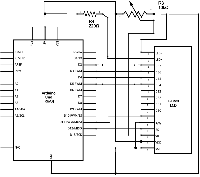
Helpful schema.
I’ll post some pictures of the wiring in a bit. Hopefully some others will find this helpful.
This is kind of an old thread but I did show up here asking some of the same questions.
Someone posted a neat diagram on the interwebs a while ago on how to hook up a 16x2 LCD in 4-bit mode.
It helped me a bit so I thought I 'd share. I don’t see why this would not work with a 16x4 because it is the same LCD controller but I haven’t actually tried it…
EDIT:: Ok, I have tried it with the 20 x 4 display in this thread and it works beautifully.You need to change this line of course:
lcd.begin(16,2) to lcd.begin(20,4).
Note that you will be using D0 and D1 for RS and EN instead of D11 and D12 as found in the Arduino tut.
Also, this tidbit from the reference sheets is helpful since most of these are 5V displays.
“When the Photon is powered via the USB port, VIN will output a voltage of approximately 4.8VDC due to a reverse polarity protection series schottky diode between V+ of USB and VIN. When used as an output, the max load on VIN is 1A.”