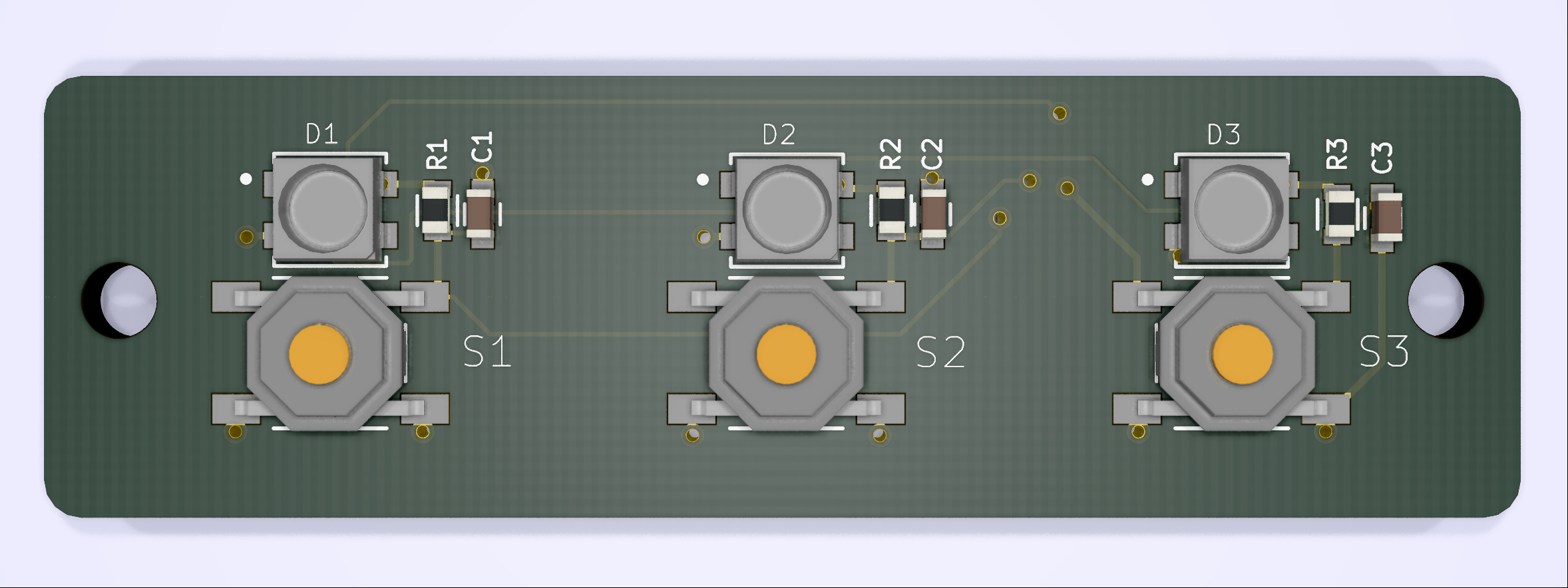


I designed a board with 3 push buttons + 3 Neopixels as indicator lights.
I’m feeding the output of the 3 buttons to 3 pins on a Photon.
Can you tell me if the schematic is OK?
I designed a board with 3 push buttons + 3 Neopixels as indicator lights.
I’m feeding the output of the 3 buttons to 3 pins on a Photon.
Can you tell me if the schematic is OK?
@RWB, it would be good decouple each Neopixel’s Vdd with a 100nF cap. Also, the RC delay you have on each button is about roughly 3-4ms which is what I am assuming you wanted. You can put a GND plane on top of the board and stitch it to the bottom. This makes SMT grounds much easier on the top. Also, I would put the switch RC beside the buttons and not next to the Neopixels. This will also give you more room for your Neopixel decoupling caps. You could create a 3.3v copper “island” on the bottom to route your supply voltage in bulk instead. If the cable from this board to where the power supply is longer than a couple of inches, you should consider adding a 10 to 22uF decoupling cap near the connector pin.
Good tip. I did not reference the Adafruit strip design which does the same so I’ll add those.
I will be dimming the brightness way down probably so will not be driving them at full power which may help.
I just copied reference schematic design from the forum. I have no idea if 3-4 ms delay is good or bad but it’s easy to put a different cap on if needed.
Thought about that but didn’t do it. Makes sense though.
I will do that.
The flex cable will only be 1 inch long at the most and Gnd and 3.3v+ are ran over multiple pins for less resistance so I didn’t feel the extra caps were necessary.
I will make the changes and report back.
Thanks for the professional advice.
@RWB, if the cable is that short then a 1uF is probably fine. Group the voltage pins so it is easy to interconnect them and add that decoupling cap.