For reference, here is the code and libraries I am using, in case it helps with troubleshooting, or in case someone else in the future wants to use them…
current_monitor.ino
/* Particle Electron current and voltage measurement using the INA226 CJMCU Breakout Board */
// ************************** Libraries Needed To Compile The Script **************************
#include <INA226.h> //library for the current and voltage sensor
#include <Ubidots.h>
#define TOKEN "mytoken" // Your unique Ubidots TOKEN. Do not share this token publicly.
Ubidots ubidots(TOKEN);
// ************ INA226 Current and Voltage Monitor Definitions *****************************************
INA226 ina;
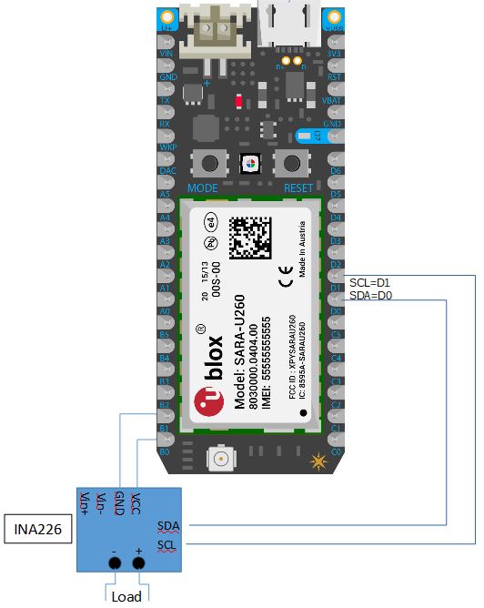
const int CurrentSensorPowerPin=B0; //current and voltage sensor power pin
const int CurrentSensorGndPin =B1; //current and voltage sensor GROUND pin
//const int CurrentSensorSDAPin =D0; //I2C communication pin
//const int CurrentSensorSCLPin =D1; //I2C communication pin
const int LightPin =D7; // light for debugging
float shuntcurrentA=0; //i7nitalize variables for INA226
float shuntvoltageV=0;
float busvoltageV=0;
float buspowerW=0;
int Reading_Delay_milliseconds=15000; // delay between readings in milliseconds.
// *********************************Setup - runs Once and sets pins etc ******************************************************
void setup()
{
//SET UP PINS FOR SENSORS:
//Serial.begin(9600); // only used for wired connection serial communication
pinMode(CurrentSensorPowerPin , OUTPUT); // set the powerpin as an output
digitalWrite(CurrentSensorPowerPin , HIGH); //Turn it on for now
pinMode(CurrentSensorGndPin , OUTPUT);//setting pin for ground for the EC sensor as an ouput
digitalWrite(CurrentSensorGndPin,LOW);//We can leave the ground connected permanantly
pinMode(LightPin , OUTPUT); // set the lightpin as an output (for troubleshooting)
// Initialize INA226 Current & Voltage Sensor. Default INA226 address is 0x40
delay(500);// gives sensor time to settle
ina.begin();
// Configure INA226:
ina.configure(INA226_AVERAGES_1, INA226_BUS_CONV_TIME_1100US, INA226_SHUNT_CONV_TIME_1100US, INA226_MODE_SHUNT_BUS_CONT);
// Calibrate INA226. (Rshunt = 0.01 ohm, Max excepted current = 4A) (Rshunt = .008 ohm, Max current=11A):
ina.calibrate(0.008, 11);
}; // ******************************************* End of Setup **********************************************************************
// *******************************************************************************************************************
// ************************************* Main Loop - Runs Forever ****************************************************
// *******************************************************************************************************************
// The main loop is run repeatedly. It calls functions for taking sensor readings, printing results, etc.
void loop()
{
digitalWrite(LightPin , HIGH); //Turn on light
GetCurrent(); //Calls code to get current and voltage
PrintReadings(); // Calls Print routine [below main loop]
digitalWrite(LightPin , LOW); //Turn off light
delay(Reading_Delay_milliseconds); //delay between readings in milliseconds.
};
// *******************************************************************************************************************
// ************************************** End Of Main Loop ***********************************************************
// *******************************************************************************************************************
// ************ GetCurrent Function (This Loop Is called From Main Loop)********************************************************
void GetCurrent(){
// reads current and voltage from the INA219 or INA229 sensor
shuntcurrentA=ina.readShuntCurrent();
shuntvoltageV=ina.readShuntVoltage();
busvoltageV=ina.readBusVoltage();
buspowerW=ina.readBusPower();
delay(500);
};
// ****** Send Readings Function (This is where useful data is sent to the desired location) ******
void PrintReadings(){
ubidots.add("Current_A", shuntcurrentA);
ubidots.add("Shunt_Voltage_V", shuntvoltageV);
ubidots.add("Bus_Voltage_V", busvoltageV);
ubidots.add("buspowerW", buspowerW);
ubidots.sendAll(); //send the variables to Ubidots
}; // *********************** END OF PROGRAM ************************
INA226.h
/*
INA226.h - Header file for the Bi-directional Current/Power Monitor Arduino Library.
Version: 1.0.0
(c) 2014 Korneliusz Jarzebski
www.jarzebski.pl
This program is free software: you can redistribute it and/or modify
it under the terms of the version 3 GNU General Public License as
published by the Free Software Foundation.
This program is distributed in the hope that it will be useful,
but WITHOUT ANY WARRANTY; without even the implied warranty of
MERCHANTABILITY or FITNESS FOR A PARTICULAR PURPOSE.  See the
GNU General Public License for more details.
You should have received a copy of the GNU General Public License
along with this program.  If not, see <http://www.gnu.org/licenses/>.
*/

#ifndef INA226_h
#define INA226_h


    //#if ARDUINO >= 100
    //#include "Arduino.h"
    //#else
    //#include "WProgram.h"
    //#endif

#include "Particle.h"


#define INA226_ADDRESS              (0x40)

#define INA226_REG_CONFIG           (0x00)
#define INA226_REG_SHUNTVOLTAGE     (0x01)
#define INA226_REG_BUSVOLTAGE       (0x02)
#define INA226_REG_POWER            (0x03)
#define INA226_REG_CURRENT          (0x04)
#define INA226_REG_CALIBRATION      (0x05)
#define INA226_REG_MASKENABLE       (0x06)
#define INA226_REG_ALERTLIMIT       (0x07)

#define INA226_BIT_SOL              (0x8000)
#define INA226_BIT_SUL              (0x4000)
#define INA226_BIT_BOL              (0x2000)
#define INA226_BIT_BUL              (0x1000)
#define INA226_BIT_POL              (0x0800)
#define INA226_BIT_CNVR             (0x0400)
#define INA226_BIT_AFF              (0x0010)
#define INA226_BIT_CVRF             (0x0008)
#define INA226_BIT_OVF              (0x0004)
#define INA226_BIT_APOL             (0x0002)
#define INA226_BIT_LEN              (0x0001)

typedef enum
{
    INA226_AVERAGES_1             = 0b000,
    INA226_AVERAGES_4             = 0b001,
    INA226_AVERAGES_16            = 0b010,
    INA226_AVERAGES_64            = 0b011,
    INA226_AVERAGES_128           = 0b100,
    INA226_AVERAGES_256           = 0b101,
    INA226_AVERAGES_512           = 0b110,
    INA226_AVERAGES_1024          = 0b111
} ina226_averages_t;

typedef enum
{
    INA226_BUS_CONV_TIME_140US    = 0b000,
    INA226_BUS_CONV_TIME_204US    = 0b001,
    INA226_BUS_CONV_TIME_332US    = 0b010,
    INA226_BUS_CONV_TIME_588US    = 0b011,
    INA226_BUS_CONV_TIME_1100US   = 0b100,
    INA226_BUS_CONV_TIME_2116US   = 0b101,
    INA226_BUS_CONV_TIME_4156US   = 0b110,
    INA226_BUS_CONV_TIME_8244US   = 0b111
} ina226_busConvTime_t;

typedef enum
{
    INA226_SHUNT_CONV_TIME_140US   = 0b000,
    INA226_SHUNT_CONV_TIME_204US   = 0b001,
    INA226_SHUNT_CONV_TIME_332US   = 0b010,
    INA226_SHUNT_CONV_TIME_588US   = 0b011,
    INA226_SHUNT_CONV_TIME_1100US  = 0b100,
    INA226_SHUNT_CONV_TIME_2116US  = 0b101,
    INA226_SHUNT_CONV_TIME_4156US  = 0b110,
    INA226_SHUNT_CONV_TIME_8244US  = 0b111
} ina226_shuntConvTime_t;

typedef enum
{
    INA226_MODE_POWER_DOWN      = 0b000,
    INA226_MODE_SHUNT_TRIG      = 0b001,
    INA226_MODE_BUS_TRIG        = 0b010,
    INA226_MODE_SHUNT_BUS_TRIG  = 0b011,
    INA226_MODE_ADC_OFF         = 0b100,
    INA226_MODE_SHUNT_CONT      = 0b101,
    INA226_MODE_BUS_CONT        = 0b110,
    INA226_MODE_SHUNT_BUS_CONT  = 0b111,
} ina226_mode_t;

class INA226
{
    public:

	bool begin(uint8_t address = INA226_ADDRESS);
	bool configure(ina226_averages_t avg = INA226_AVERAGES_1, ina226_busConvTime_t busConvTime = INA226_BUS_CONV_TIME_1100US, ina226_shuntConvTime_t shuntConvTime = INA226_SHUNT_CONV_TIME_1100US, ina226_mode_t mode = INA226_MODE_SHUNT_BUS_CONT);
	bool calibrate(float rShuntValue = 0.1, float iMaxExcepted = 2);

	ina226_averages_t getAverages(void);
	ina226_busConvTime_t getBusConversionTime(void);
	ina226_shuntConvTime_t getShuntConversionTime(void);
	ina226_mode_t getMode(void);

	void enableShuntOverLimitAlert(void);
	void enableShuntUnderLimitAlert(void);
	void enableBusOvertLimitAlert(void);
	void enableBusUnderLimitAlert(void);
	void enableOverPowerLimitAlert(void);
	void enableConversionReadyAlert(void);

	void setBusVoltageLimit(float voltage);
	void setShuntVoltageLimit(float voltage);
	void setPowerLimit(float watts);

	void setAlertInvertedPolarity(bool inverted);
	void setAlertLatch(bool latch);

	bool isMathOverflow(void);
	bool isAlert(void);

	float readShuntCurrent(void);
	float readShuntVoltage(void);
	float readBusPower(void);
	float readBusVoltage(void);

	float getMaxPossibleCurrent(void);
	float getMaxCurrent(void);
	float getMaxShuntVoltage(void);
	float getMaxPower(void);

    private:

	int8_t inaAddress;
	float currentLSB, powerLSB;
	float vShuntMax, vBusMax, rShunt;

	void setMaskEnable(uint16_t mask);
	uint16_t getMaskEnable(void);

	void writeRegister16(uint8_t reg, uint16_t val);
	int16_t readRegister16(uint8_t reg);
};

#endif
INA226.cpp
/*
INA226.cpp - Class file for the INA226 Bi-directional Current/Power Monitor Arduino Library.
Version: 1.0.0
(c) 2014 Korneliusz Jarzebski
www.jarzebski.pl
This program is free software: you can redistribute it and/or modify
it under the terms of the version 3 GNU General Public License as
published by the Free Software Foundation.
This program is distributed in the hope that it will be useful,
but WITHOUT ANY WARRANTY; without even the implied warranty of
MERCHANTABILITY or FITNESS FOR A PARTICULAR PURPOSE.  See the
GNU General Public License for more details.
You should have received a copy of the GNU General Public License
along with this program.  If not, see <http://www.gnu.org/licenses/>.
*/

    //#if ARDUINO >= 100
     //#include "Arduino.h"
    //#else
     //#include "WProgram.h"
    //#endif
#include "Particle.h"

#include "INA226.h"

bool INA226::begin(uint8_t address)
{
    Wire.begin();
    inaAddress = address;
    return true;
}

bool INA226::configure(ina226_averages_t avg, ina226_busConvTime_t busConvTime, ina226_shuntConvTime_t shuntConvTime, ina226_mode_t mode)
{
    uint16_t config = 0;

    config |= (avg << 9 | busConvTime << 6 | shuntConvTime << 3 | mode);

    vBusMax = 36;
    vShuntMax = 0.08192f;

    writeRegister16(INA226_REG_CONFIG, config);

    return true;
}

bool INA226::calibrate(float rShuntValue, float iMaxExpected)
{
    uint16_t calibrationValue;
    rShunt = rShuntValue;

    float iMaxPossible, minimumLSB;

    iMaxPossible = vShuntMax / rShunt;

    minimumLSB = iMaxExpected / 32767;

    currentLSB = (uint16_t)(minimumLSB * 100000000);
    currentLSB /= 100000000;
    currentLSB /= 0.0001;
    currentLSB = ceil(currentLSB);
    currentLSB *= 0.0001;

    powerLSB = currentLSB * 25;

    calibrationValue = (uint16_t)((0.00512) / (currentLSB * rShunt));

    writeRegister16(INA226_REG_CALIBRATION, calibrationValue);

    return true;
}

float INA226::getMaxPossibleCurrent(void)
{
    return (vShuntMax / rShunt);
}

float INA226::getMaxCurrent(void)
{
    float maxCurrent = (currentLSB * 32767);
    float maxPossible = getMaxPossibleCurrent();

    if (maxCurrent > maxPossible)
    {
        return maxPossible;
    } else
    {
        return maxCurrent;
    }
}

float INA226::getMaxShuntVoltage(void)
{
    float maxVoltage = getMaxCurrent() * rShunt;

    if (maxVoltage >= vShuntMax)
    {
        return vShuntMax;
    } else
    {
        return maxVoltage;
    }
}

float INA226::getMaxPower(void)
{
    return (getMaxCurrent() * vBusMax);
}

float INA226::readBusPower(void)
{
    return (readRegister16(INA226_REG_POWER) * powerLSB);
}

float INA226::readShuntCurrent(void)
{
    return (readRegister16(INA226_REG_CURRENT) * currentLSB);
}

float INA226::readShuntVoltage(void)
{
    float voltage;

    voltage = readRegister16(INA226_REG_SHUNTVOLTAGE);

    return (voltage * 0.0000025);
}

float INA226::readBusVoltage(void)
{
    int16_t voltage;

    voltage = readRegister16(INA226_REG_BUSVOLTAGE);

    return (voltage * 0.00125);
}

ina226_averages_t INA226::getAverages(void)
{
    uint16_t value;

    value = readRegister16(INA226_REG_CONFIG);
    value &= 0b0000111000000000;
    value >>= 9;

    return (ina226_averages_t)value;
}

ina226_busConvTime_t INA226::getBusConversionTime(void)
{
    uint16_t value;

    value = readRegister16(INA226_REG_CONFIG);
    value &= 0b0000000111000000;
    value >>= 6;

    return (ina226_busConvTime_t)value;
}

ina226_shuntConvTime_t INA226::getShuntConversionTime(void)
{
    uint16_t value;

    value = readRegister16(INA226_REG_CONFIG);
    value &= 0b0000000000111000;
    value >>= 3;

    return (ina226_shuntConvTime_t)value;
}

ina226_mode_t INA226::getMode(void)
{
    uint16_t value;

    value = readRegister16(INA226_REG_CONFIG);
    value &= 0b0000000000000111;

    return (ina226_mode_t)value;
}

void INA226::setMaskEnable(uint16_t mask)
{
    writeRegister16(INA226_REG_MASKENABLE, mask);
}

uint16_t INA226::getMaskEnable(void)
{
    return readRegister16(INA226_REG_MASKENABLE);
}

void INA226::enableShuntOverLimitAlert(void)
{
    writeRegister16(INA226_REG_MASKENABLE, INA226_BIT_SOL);
}

void INA226::enableShuntUnderLimitAlert(void)
{
    writeRegister16(INA226_REG_MASKENABLE, INA226_BIT_SUL);
}

void INA226::enableBusOvertLimitAlert(void)
{
    writeRegister16(INA226_REG_MASKENABLE, INA226_BIT_BOL);
}

void INA226::enableBusUnderLimitAlert(void)
{
    writeRegister16(INA226_REG_MASKENABLE, INA226_BIT_BUL);
}

void INA226::enableOverPowerLimitAlert(void)
{
    writeRegister16(INA226_REG_MASKENABLE, INA226_BIT_POL);
}

void INA226::enableConversionReadyAlert(void)
{
    writeRegister16(INA226_REG_MASKENABLE, INA226_BIT_CNVR);
}

void INA226::setBusVoltageLimit(float voltage)
{
    uint16_t value = voltage / 0.00125;
    writeRegister16(INA226_REG_ALERTLIMIT, value);
}

void INA226::setShuntVoltageLimit(float voltage)
{
    uint16_t value = voltage * 25000;
    writeRegister16(INA226_REG_ALERTLIMIT, value);
}

void INA226::setPowerLimit(float watts)
{
    uint16_t value = watts / powerLSB;
    writeRegister16(INA226_REG_ALERTLIMIT, value);
}

void INA226::setAlertInvertedPolarity(bool inverted)
{
    uint16_t temp = getMaskEnable();

    if (inverted)
    {
        temp |= INA226_BIT_APOL;
    } else
    {
        temp &= ~INA226_BIT_APOL;
    }

    setMaskEnable(temp);
}

void INA226::setAlertLatch(bool latch)
{
    uint16_t temp = getMaskEnable();

    if (latch)
    {
        temp |= INA226_BIT_LEN;
    } else
    {
        temp &= ~INA226_BIT_LEN;
    }

    setMaskEnable(temp);
}

bool INA226::isMathOverflow(void)
{
    return ((getMaskEnable() & INA226_BIT_OVF) == INA226_BIT_OVF);
}

bool INA226::isAlert(void)
{
    return ((getMaskEnable() & INA226_BIT_AFF) == INA226_BIT_AFF);
}

int16_t INA226::readRegister16(uint8_t reg)
{
    int16_t value;

    Wire.beginTransmission(inaAddress);
                //#if ARDUINO >= 100
            Wire.write(reg);
                //#else
                //    Wire.send(reg);
                //#endif
    Wire.endTransmission();

    delay(1);

    Wire.beginTransmission(inaAddress);
    Wire.requestFrom(inaAddress, 2);
    while(!Wire.available()) {};
                //#if ARDUINO >= 100
        uint8_t vha = Wire.read();
        uint8_t vla = Wire.read();
                //#else
                    //uint8_t vha = Wire.receive();
                    //uint8_t vla = Wire.receive();
                //#endif;
    Wire.endTransmission();

    value = vha << 8 | vla;

    return value;
}

void INA226::writeRegister16(uint8_t reg, uint16_t val)
{
    uint8_t vla;
    vla = (uint8_t)val;
    val >>= 8;

    Wire.beginTransmission(inaAddress);
    //#if ARDUINO >= 100
        Wire.write(reg);
        Wire.write((uint8_t)val);
        Wire.write(vla);
   // #else
        //Wire.send(reg);
        //Wire.send((uint8_t)val);
        //Wire.send(vla);
    //#endif
    Wire.endTransmission();
}
UPDATE: excess #include statements removed from libraries above per ScruffR’s comment.