I am currently working with a Particle electron board and two MAX31865, I need to read two thermocouples, I know that we can use PIN A0 and A1, to indicate that MAX31865 board I want to read, using SPI, but I can’t read any of the MAX31865, someone will have Any example of how to activate the communication bus?
This is the code that I am currently working on
#include <Adafruit_MAX31865.h>


// Use software SPI: CS, DI, DO, CLK
Adafruit_MAX31865 sensor = Adafruit_MAX31865(A2, A5, A4, A3);
// use hardware SPI, just pass in the CS pin
//Adafruit_MAX31865 max = Adafruit_MAX31865(A2);
SYSTEM_MODE(MANUAL);
// The value of the Rref resistor. Use 430.0!
#define RREF  430.1

const int SPI_PINA0 = A0;
const int SPI_PINA1 = A1;

void Producttemp_sensor();
void Glycoltemp_sensor();

void setup() {
  Serial.begin(115200);
  Serial.println("Adafruit MAX31865 PT1000 Sensor Test!");

  sensor.begin(MAX31865_2WIRE);  // set to 2WIRE or 4WIRE as necessary

  pinMode(SPI_PINA0, OUTPUT);
  pinMode(SPI_PINA1, OUTPUT);

}


void loop()
{
  uint16_t rtd = sensor.readRTD();
  Producttemp_sensor();

  Serial.print("RTD value: "); Serial.println(rtd);
  float ratio = rtd;
  ratio /= 32768;
  Serial.print("Ratio = "); Serial.println(ratio,8);
  Serial.print("Resistance = "); Serial.println(RREF*ratio,8);
  Serial.print("Temperature = "); Serial.println(sensor.temperature(100, RREF));

  // Check and print any faults
  uint8_t fault = sensor.readFault();
  if (fault) {
    Serial.print("Fault 0x"); Serial.println(fault, HEX);
    if (fault & MAX31865_FAULT_HIGHTHRESH) {
      Serial.println("RTD High Threshold");
    }
    if (fault & MAX31865_FAULT_LOWTHRESH) {
      Serial.println("RTD Low Threshold");
    }
    if (fault & MAX31865_FAULT_REFINLOW) {
      Serial.println("REFIN- > 0.85 x Bias");
    }
    if (fault & MAX31865_FAULT_REFINHIGH) {
      Serial.println("REFIN- < 0.85 x Bias - FORCE- open");
    }
    if (fault & MAX31865_FAULT_RTDINLOW) {
      Serial.println("RTDIN- < 0.85 x Bias - FORCE- open");
    }
    if (fault & MAX31865_FAULT_OVUV) {
      Serial.println("Under/Over voltage");
    }
    sensor.clearFault();
  }
  Serial.println();
  delay(10000);
}


void Producttemp_sensor()
{

    digitalWrite(SPI_PINA0, LOW);
}


void Glycoltemp_sensor()
{
    digitalWrite(SPI_PINA0, LOW);
    digitalWrite(SPI_PINA0, HIGH);
}
Have you searched the forum for MAX31865 and tried out any suggestions given in the threads found?
Why are you using software SPI instead of hardware?
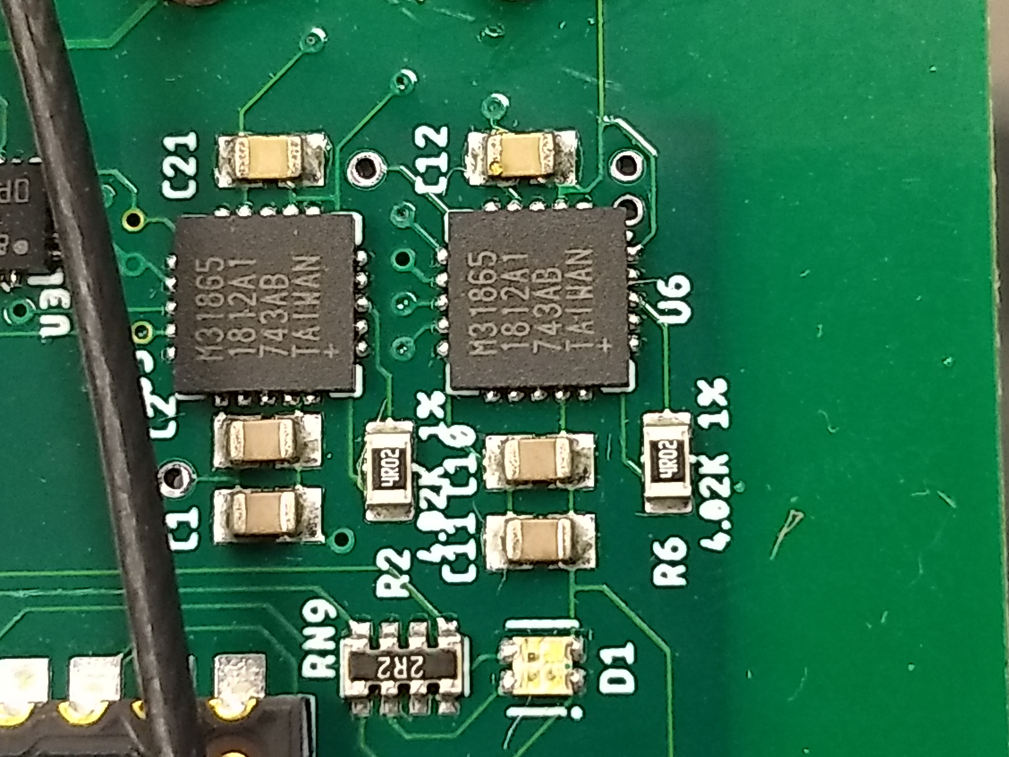
Which exact sensor board are you using?
How have you wired the sensors?
How do your cut/solder jumpers on the sensor boards look?
I don't argue SPI but why a "make-shift" software implementation when the Electron features a hardware interface for that?
Seeing this is a custom board a schematic how the two chips are wired would help.
Your code is using MAX31865_2WIRE but are the sensors actually setup for that or rather for 3WIRE or 4WIRE?
How is the Electron connected to the custom board?
Do they share common ground?
Why are you using A2 as CS pin for the sensor object while you indicate the sensors would be using A0 and A1 instead ?
...
Yes, a common point is used, so I am trying to use A0 and A1 to indicate which thermocouple I want to read.
we are only using two wires in each sensor.
Update:
I now see that you have a multiplexer/decoder chip that selects one of three SS pins depending on A0 and A1, so you’d need to check the MAX31865 library whether how it would cope with handling two sensors with one instance.
However, you’ll need to call sensor.begin() for each individual sensor and it would be good practice to check the return value of these calls.
BTW, I think you should also change the functions that select your sensor. Producttemp_sensor() should always set both pins and Glycoltemp_sensor() should probably not use the same pin twice.
previous (outdated) suggestion before the update
If SS_5 & SS_6 in the schematic correspond to A0 & A1 respectively you should probably alter your code this way
As the caption said, that was my first impression when I just looked at the schematic showing the sensors, but then after I also looked at the other schematic that LS74LVC caught my attention and rendered that suggestion irrelevant.
You still can have two sensor objects, but they are not allowed to use A0 and A1 as that would cause the wrong SPI slaves to be selected due to the indirectionality introduced by that multiplexer/decoder.
With that you’d need to do something along this line
SYSTEM_MODE(MANUAL);
SYSTEM_THREAD(ENABLED);       // not requierd but most the time good to have

SerialLogHandler logger(LOG_LEVEL_ALL);

const int SPI_DUMMY_CS = A2;  // must stay unconnected
const int SPI_PINA0    = A0;
const int SPI_PINA1    = A1;

enum CHIP_SELECT
{ csPRODUCT = 0  // A1 LOW , A0 LOW
, csGLYCOL  = 1  // A1 LOW , A0 HIGH
, csACCEL   = 2  // A1 HIGH, A0 LOW
, csNONE    = 3  // A1 HIGH, A0 HIGH
};

Adafruit_MAX31865 sensor(SPI_DUMMY_CS);

void selectSensor(CHIP_SELECT selection = csNONE);
...
void setup() {
  ...
  selectSensor(csPRODUCT);
  if (!sensor.begin())
    Log.error("ProductTemp sensor failed");

  selectSensor(csGLYCOL);
  if (!sensor.begin())
    Log.error("GlycolTemp sensor failed");

  selectSensor(csNONE);
  ...
}
...
void selectSensor(CHIP_SELECT selection) {
  digitalWrite(SPI_PINA0, selection & 0x01);
  digitalWrite(SPI_PINA1, selection & 0x02);
}
I don’t know how the MAX31865 will cope with the CS line being held LOW for the entire time selectSensor() keeps it enabled.
I also haven’t fully read the datasheet of the LS74 chip whether the CS lines will be treated active LOW or HIGH. If it’s the wrong way round, the CHIP_SELECT enum may need correcting.
I believe that for the library to work, it will need to be modified to support the muxed CS selection. Returning the CS to HIGH for both devices will ensure the SPI is properly “floated” between transactions. So, in the constructor, instead of CS representing a specific GPIO pin, it would represent the A0/A1 bit pair combination to select the specific device. A simple function or macro could be added to the library to set the A0/A1 GPIO pair.
This would be the intent of my proposed selectSensor(csNONE), but for that the LS74LVC would need to treat the fourth state in a way to either tri-state (and additional pull-ups would need to pull the CS lines high) or if it could be set to default to HIGH on all output lines.
But as said, I haven't dug into the datasheet of that chip to be sure.
@eavendano, you could ask the board designer about the default behaviour of the multiplexer, so that we don't have to investigate that matter
What will be the levels on Y0, Y1 and Y2 for the four combinations of A0 & A1?
@ScruffR, great thoughts but at the cost of a “dummy” CS pin (A2). Modifying the library is “free” and insulates the app from having to set the CS lines.
As for the state of the pins, the datasheet shows:
Each state is mutually exclusive except for A1=L where A0 can be high or low. It might be a good idea to have a global device selection function that can be called from the modified MAX31865 library and the user code. This function could be called with a device number to set a unique CS pin LOW and reset to have a selected device remain active on the SPI bus due to the nature of the mux and hardware design.
If I understand correctly, the third output of the mux goes to a tri-state buffer, driving its output LOW or floating to enable an accelerometer. I am not sure what the logic is behind this design decision.
As it seems there will be always one slave selected since the /G input can't be controled which would be the only way to drive all three output pins HIGH.
@ScruffR, having a single device “selected” is fine as long as (and you eluded to this), whatever device is left is this state is not adversely affected. In a single SPI device environment, it is common to tie its CS pin to GND.
Based on my previous statement on the “third” CS, I would suspect that device needs to be deselected with its CS pin floating, otherwise I don’t see any reason for the 74LVC2G125 being there. Perhaps @eavendano can clarify.
That was my stance for some time too, but although I can't quite remember which device that was (years back), but I've dealt with some sensor/chip that needed to be deselected between two readings otherwise the readings didn't get updated.
That was some debugging effort till I found that out - ever since I'm extra cautious
@ScruffR I already asked the designer and he sent me the same table that shows @peekay123
@peekay123 the designer explained to me that having three readings to take, him make the decision of that design, are the readings of two thermocouples and an accelerometer.
@ScruffR@peekay123 I checked the circuit of the Max31865 and found that the reference resistance value is wrong, the designer will make the change and we will be testing again, thanks for your time.