Hacking a Nespresso Machine! | Brewno

Hi All… I am looking for a good mechanic hacker… I have a Nespresso Machine I want to make WiFi capable.

The electronics part is mostly done, The board will handle the Photon, the High Loads of the boiler, temperature PID, fluid counter, etc. It’s tested and its working fine! It makes coffee real good!

However… The mechanical Part is a PIA!.. I managed to 3d print a dispenser of the capsules that works fine, the cartage dispensing it’s mostly done too.

It’s the opening and closing of the machine to receive the cartages that its making me go nuts… not easy at all and need a new perspective to tackle the problem. I have tried high torque servos in sync on both sides, but the force required to close and open the machine compartment to load the coffee cartages is too much of the servos in a straight in configuration… (see the 3D drawings)…

I need help! A mechanical hacker that can see things differently to tackle the issue…

Any suggestions would be welcomed since I am brain frozen!

The finished PCB board with all the TRIACS and all:
https://community.particle.io/uploads/particle/original/9/d/9d825cdc9542e1648045a7843f2b859e5a558b92.jpg

The machine:
Its a Nespresso Inissia:

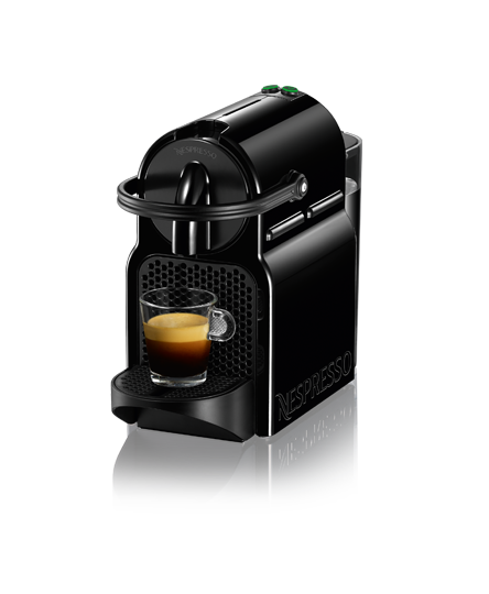
As you can see the handle on top is the one that needs to move 90 degrees up/down to open the machine loader to load a cartage and then close it… I might need stronger motors or maybe a rod with a screw but that will complicate the mechanics a lot… I am not a mechanic so… As you can see… I might be reciting stupid things :smile:

Any help would be appreciated a lot! I have a 3D printer that can be used to make parts and I am good with 3D design with Fusion 360… So… Shoot your ideas!! It will be FUN! If you like the project I can share all the files and open source it…

Here’s what I have tried so far, The first attempt worked better, but needed better servos… Tried better servos but the machine moved a lot with the torque being applied… the second was a mess with the gears, the whole machine moved too and the adjustment of the teeth was very difficult… So I might need to anchor the servo to the same machine, instead of all the way from the bottom, or use another idea completely…

Try 1:

Try 2:

Thanks!

2 Likes

You could use a linear actuator. One side on the handle, and the other side on the 3D printed shell. I don’t think it will be more complex than servos.
Do you have an idea of the force needed to move the handle?

By the way: nice 3Ds !

Thanks!

I don’t know in terms of force how much. Is there a simple way to measure it!?

Thing is that the handle as it is now needs to go because it will interfere with the drop of the capsule. And if you try to rotate from the center it requires much more force.

Any recommendations of linear actuators? Where to get them?

Maybe a screw stepper motor. You’d need a stepper controller as well though, or 2 sets if you need it on both sides.

I think that since I don’t need position control, I might find a DC MOTOR / GEAR that will produce more torque than a Stepper???

Yeah, gear motors are strong and maybe cheaper. Screw steppers are strong as well, and you can control the travel a little easier. With a gear motor you’d probably need a limit switch on each end position, or one end and time it going the other way.

I will try a servo motor once again… If it does not work, il go to gear motors with potentiometers or limit switches as you recommend.

For moving the handle it’s a question of torque. If I had to measure it, I’d go the old fashioned way:

  1. Tie string to handle
  2. Run string over pulley centered on coffee machine COM (assumption: your device won’t be much larger than the coffee machine)
  3. Add weight to other end of string until handle completes motion

This will get you, therefore, a ballpark (read: sketchy) estimate on average torque required when you go shopping for motors:

T = M*g*R

M = mass required to pull handle (kg)
g = 9.81 (m*s^-2)
R = radius of handle (m)

Because when you consider geometries of applying this torque, you can tweak your radius and required force, but the critical torque (enough to rotate the axle) should be a conserved quantity.

A worm drive (or worm gear) might be what you need - you have a motor attached essentially to a screw thread, which meshes in the teeth of a gear wheel. It’s a compact way of achieving very high torque (at the expense of rotational speed). There seem to be a few likely looking ones available on eBay, with the gears enclosed in a nice solid-looking box. Note you’d need some limit switches (or an optical sensor) to control the travel (unlike a stepper motor).

I’m wondering why it needs torque. Is it because it’s off-balance or difficult to move? If it’s off balance, then a spring or counter-balance could be used. Or if it’s lift, then as @msolters said, a counter-weight like an elevator, or a torsion spring like garage doors or car windows might do it. Or does it need to shut really tight?

It needs force because at the end it has a click it needs in order to seal the water from coming out upon pumping…

The coulterweight don’t seem feasible… At least in my imagination…

Right now I am on either the geared motor or the worm drive…

Have you thought about changing the design? Like have the top slide in/out like a CD tray and seal a different way, or just the way the lid seals without snapping?

I am taking a look at that but it will involve a major dissambly…

Thanks

I think the force is pushing the capsule onto the spikes that puncture the aluminum, three on on the back and a mesh arrangement at the front. I wonder if a solenoid would be best? they generally have a very fast action, you could use PWM to reduce the holding power once its moved fully.
Something like this one
http://www.jaycar.com.au/Electromechanical-Components/Mechatronics/Solenoids/Standard-12V-Solenoid/p/SS0902

Thank you all. I am worklng in a direct drive straight coupled to the machine first. I am using two high torque servos. If that works it would be the simplest solution… If it does not, il try the solenoid and the worm drive ideas.

Il keep everyone posted!
Thanks for the help!

How do you envision we can get more travel than what it is depicted in the specs?

I think it will need something like 30 to 40 mm

it depends where you attach it, if you can move it closer to the pivot point it doesn’t need to move as far. maybe one on each side? and a spring to pull it back up? or remove the mechanism and mount it internally, all the bar does is pulls the front in by 5-10mm to puncture the capsule…

and is the pivot point a single bar? can you drive it from just one side? or are there 2 separate drive mechanisms?

Check out how people make DIY cnc routers, etc. Attach a motor to a threaded rod, then attach a nut to the handle. As the motor turns one way, the nut will push open the handle, as the motor turns the other, it will pull it closed. The motor will need to pivot some, which just means more 3d printing :smiley: . You don't really need a "servo" that's overkill, you need 2 limit switches, because all you need to know is when your handle is all the way open and all the way closed.

Check out this page if you still want to think about a servo - there's not much to a servo but a dc motor, an h-bridge motor driver, a potentiometer, and some gears. The only thing that's all that smart is a servo is taking the PWM signal and converting that into angular degrees. With the Photon, you can just read the pot value directly and turn off power to the motor when you are near that value. Servos use PID algorithms to slow the speed of rotation as they near their setpoint, but that also seems like overkill.

1 Like

@jrubins and everyone!! Great recommendation!! I’m finishing a print tonight… If everything goes according to plan… I am testing the solution of the servo tonight… I know it’s an overkill… But it’s what I have on hand‼️

@msolters I appreciate the formula and the method… This is now safe in my formula notebook for future use‼️ Question: will this result be the torque required at the radius of the handle or at the center of the axle or pivot point, where the handle applies force… Eg: will the torque contemplates the lever or not… Thanks!!

@frlobo Torque is a cross product between an applied force, and some radius vector. As such, the same torque can be accomplished with different combinations of force and radius.

In the example I gave, we are seeking to determine the critical torque required to complete the pod-pressing action by using the handle, in which case we are computing our estimate by considering the radius of the handle from the axis it rotates when you push it.

If you rotate the axle directly with some form of electromagnetically propelled device, like a motor, then your acting radius is much smaller, and your effective force will be linearly greater in order to produce that same torque.

In practice, it doesn’t matter, as long as the motor can supply the right torque, and you do not construct too elaborate of an intermediate simple machine that dissipates all that work.

I am not recommending a counter-weight as a mechanism to power this motion, I am recommending it as a trivially simple way to measure how strong of a motor you would need to buy to do the same, directly at the axle. Whatever torque gravity tugging on a string applied at the radius of the handle generates, that’s the same torque you’d need at the axle, and the same torque you’d need using a lever twice as big!

2 Likes