Will I damage anything connecting the shield power inputs (@5.4v max) directly to the LiPo battery connector on the Electron as shown in the green circle above?
If not, is it reasonable to expect the Electron board to run normally?
Will I damage anything connecting the shield power inputs (@5.4v max) directly to the LiPo battery connector on the Electron as shown in the green circle above?
If not, is it reasonable to expect the Electron board to run normally?
I wouldn’t do it.
I’d rather add some buffer caps to deal with the power spikes.
Don’t do it!
I blew up the 3.3V converter on a Photon by powering a stepper from the Vin pin to the Photon.
Luckily that’s all that broke.
What worked for me was adding 47uF and a diode in series with the motor power pin. That
way the motor cannot feed voltage back to the cap… at least in one direction.
I'd try this instead:
Powering your entire system "may" be possible with only using the Li-Po connector (it's withing the max Spec), and the neopixels tapped before the Electron, but several people here have made recommendations against going much higher than the typical Li-Po 4.2V max voltage on the Li-Po connector.
I certainly wouldn't want to connect the Screw Terminals to the Li+ pin, or Li-Po connector as shown in your Green Circles.
The Screw Terminals are Labeled for 12V max, since it's essentially Vin I believe. That's asking for trouble later-on if you tie that to your Li-Po circuitry (even when you don't plan on using a Li-Po).
Have you measured the instantaneous peak current during switch closure, with all your gadgets firing up at once?
If Caps are needed (per @ScruffR), they will be needed no matter where you land your battery source.
You might also want to test with batteries at ~ 50% capacity, before deployment. That may reinforce the idea of using Caps ?
I understand what it’s for, but I don’t know how to size a cap or where to hook it up?
The asset tracker spec sheet says it will run just using the shield terminals without the LiPo, but nothing I try seems to work.
(I have not tried a car battery, but that’s really not an option)
I “MAY” be on to something…
I just hooked it up with only the shield terminals (5.4 batt) and the USB charging cable
I did not connect the electron’s LiPo battery
Everything worked correctly!!!
SO… I’m thinking I can take an old USB cable and hook just the +5v and GND wires to the screw terminals which are +5.4 max?
What I don’t know is if 5.4v is too much for the USB connection?
The USB Vcc/VUSB goes via a Schottky diode to Vin which is rated for 12V (plus plenty of safety).
The USB connector will block the GPS antenna on the Asset Tracker.
@ScruffR Am I correct in my assumption that the only difference in Powering the Asset Tracker with it’s Screw Terminals is the additional Schottky Diode circled below ( vs Vin) ?
I assume that diode’s only purpose is for reverse polarity protection of the Screw Terminals ?
If this is causing his problems (due to peak demands), isn’t it possible to test this theory by going Straight to Vin ?
You are correct.
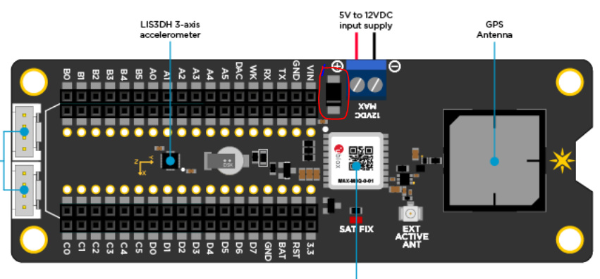
You can find the schematics here
https://github.com/particle-iot/shields/blob/master/electron-shields/asset-tracker/pdfs/asset-tracker-v200.pdf
This cable looks like it may not get that close to the GPS antenna?
Not hard... Grab the largest cap you have available and try it. The cap should probably be in the hundreds of uF (maybe a 470uF would work). If it doesn't, try larger. You can get "super caps" in the 1-10F range. I have a bunch. I would take a quick look at the discharge response curves... but, in general, a cap should be much quicker to discharge than a battery. Hook the cap between the 3.3v pin and ground.
Partly true 
Usually the larger the cap the slower the response. That’s especially true for super caps.
I usually tend to add a combination of “staggered” cap values (e.g. smaller ~100nF+ tantalum or ceramic and bigger 100µF+ electrolytic).
What do you guys think of the feasibility going directly from the screw terminals on the shield to the micro-USB of the electron with a right angle micro plug?
Will this get me past the hurdle of powering everything from 3 AA LiOn batteries? (and not fry my boards)
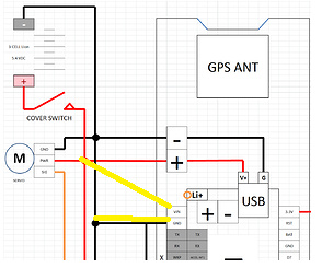
Try going straight to Vin and Ground..... not using the Screw Terminals.
See Below:
Try Just the "Yellow" Connections below for Vin and Ground: