The drawback is that FRAM is expensive.
dkryder,
Not off topic at all. Very interesting.
I think that the biggest drawback is cost / mb as peekay123 points out and for the phone example, this is also an issue of density.
However, for my little device, I have figured out how to carve up and use the 256k very efficiently and can store almost a year’s worth of hourly data. Since I am not buying a large amount of storage the cost issue is not as acute. Also, FRAM does not need a battery backup like NVSRAM. I have been using FRAM for a couple years now and am very happy with the results especially in outdoor uses where there are significant temperature swings.
Always open to new ideas, what technology technology do you use?
Chip
[slaps forehead] well, that explains it.
Chip, i have not used external memory chips in my projects yet, although from what i’ve learned in this thread that may change in future ones. currently i use sd cards if i want to save data. i like being able to move the data easily between devices. although now that i think about it there probably could be scripts to transfer the FRAM contents to other devices.
Dkrider,
I started with MicroSD way back but there were two big limitations which caused me to switch to FRAM:
- MicroSD cards draw up to 500mV briefly when writing. I was operating on a low (Solar) power budget so, I wanted a more energy efficient option.
- The libraries for MicroSD were based on a FAT file system. I could append data to a file but I could not easily work with data directly. With Ram, you can segment the memory to store the state of the system, variables and data. With this approach, my device could lose power and restore automatically to the state where they left off. Not sure how to do this with MicroSD.
Hope this helps.
Chip
@chipmc, microSDs can draw a lot of current and I have found some still draw considerable current in standby as well. The biggest driver for microSD is the huge storage available. As for managing data, using the SDFat library with binary files allows for structured data storage (binary file) allowing you to work with data “directly”. Using SDFat requires careful consideration of where to store persistent data pointers, etc.
The main driver for using hardware FRAM, flash or eeprom for me is the mechanical resilience versus microSD. In industrial applications where vibrations are an issue, these are not optional. FRAM’s speed and zero write-wearing are only outweighed by the size limitation and their costs. I have started working with 512 and 1024 Mbyte SPI external flash chips using SPIFFS (SPI flash file system) and though it is limited in speed vs FRAM and SD, in most (if not all) applications, this is fine. I don’t have enough data to say if this approach is good or not just yet. 
Rough Layout
All, before I spend too much time hand tuning, I wanted to share what the general layout is looking like. The board is 3.75" x 1.35" and will cost $25 for three from OSHPark. Don’t order yet as I need to do all the electrical and design checks. I also want to use more pours for the power path. Still, from folks who have used this device more than I, is this a reasonable layout. Headers, connectors and power on one side and all the surface mount components on the other.
Now if I could only get the Particle Dev to compile for me…


@chipmc, some of the trace widths for power seem small (eg. D1, varistors). You might want more GND vias on the JST. Not sure why D1 is in the middle of the board vs next to the connector. Otherwise layout looks good.
peekay123,
Agreed. Will increase the trace widths for power and move that D1. I think I will also try to move the varistors closer to their connectors.
Thank you for taking a look.
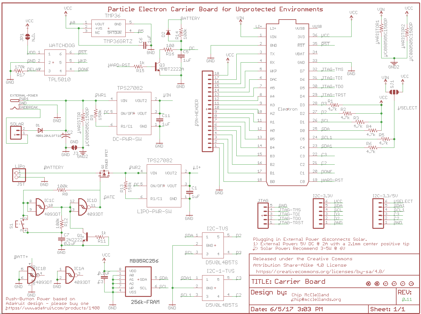
Also, I added a temperature sensor as I am a bit worried about how hot this board could get after reading some other posts. Here is the final schematic. Need to start using multiple sheets.
I don’t have an Electron Board but this is just a suggestion to reduce the labor involved in connecting things together. I see you have an 18 pin connector for what I presume is an interface to some remote io circuitry. Whenever I connect to a remote circuit with several wires involved I use a double pin header which allows using a ribbon cable connector that is fast and easy to wire up as opposed to handling individual cables. I also always add redundancy by using a few extra lines and double up conductors on the power (gnd,V+) to reduce voltage drops.
Regards Denis
Denis,
- Double row of pins to support a ribbon cable connection. I like this idea a lot but may wait for v2 when I have a better idea of what specific IO circuitry I will need. At this point was just looking to solder wires into the unpopulated header pins and start using the circuit.
- I will definitely be beefing up the power traces and adding lines.
Thank you for taking a look. Especially the ribbon cable idea.
Chip
All,
I have sent the first version to OSHPark and will keep you all posted on my testing. If all works, I will document the full bill of materials. I built this to be hand solderable however, let me know if you are interested in a finished board for purchase. If there is enough interest, I will create a Tindie listing.
OSHPark Listing: https://oshpark.com/shared_projects/Ks6U59Om


Carrier board update,
Well, I always learn something on Rev 1. Here is a status on my testing:
- Physical design - need to drop the barrel connector. It is too big and JST is polarized, cheaper, and more secure
- USB cable - Need to change the layout to give the USB connector more room especially if you don’t want to use headers
- Push button on-off - love it but decided to loose the P-MOSFET and simply use the TI High-Side switches. Less parts, less cost and a much more efficient path for the reverse current of charging as there is no body diode loss. See attached schematic
- FRAM - check - works perfectly
- Watchdog timer - need to test this.
- headers for i2c - check
- TVS and Varistor circuit protection - need to come up with a way to test this that does not fry a $69 Electron.
More updates as I get them and - as always - comments and suggestions welcome. Should have a new board design out to OSHPark by the end of the week.

Thanks,
Chip
There is always room for improvement.
Is OshPark offering you the ability to get the PCB boards shipped quicker for a higher cost on checkout? That was something they were testing last time I ordered some boards last year. Curious if it’s a standard offer now or not.
RWB,
Yes, The more I can use these devices in the field, the more ideas I have for improvement. Also, I make just as many stupid mistakes as the next person.
OSHPark does now have standard offerings for quicker turns and for faster shipping.
I think I will take one more spin on this board and try for a Medium run which (when you buy 10) brings the cost down by 80%!
Chip

Sweet.
I also put my Electron into the same type clear Pelican case with the rubber seal.
I wonder if you will see condensation inside the case once you leave it outside for awhile.
I had drilled a hole in the top of the clear lid for the solar panel wiring and then sealed the hole with silicone so I know it was really sealed but I still saw condensation build up inside the case over time. The Electron worked just fine and never rusted up or anything but maybe a few of the moisture packets thrown in to soak up moisture would be a good idea?
RWB,
I saw some condensation issues with these boxes as well. I now use them for my development boards that travel with me so I can work on a project while on the road. I think the issue is that you cannot make them 100% air tight in part because of the pressure relief valve.
When I place my sensors in the park, I use this box and put waterproof seals on every wire. Since I have done this, I have no seen condensation even in boxes that have been out for two years.
As for putting a desiccant in the box, I think that would work for a while but, eventually it would become saturated. I think going fully air tight is the only long term solution.
Thanks, Chip
@chipmc, Couple of things I noticed.
A) The solar connection has the + side (pin1) going to the GND BREAK.
B) Might be splitting hairs here, what is your reasoning for using D1? At first glance it seems to prevent back feed from external power to feed back to the solar panel. But yet you have it routed to the GND BREAK pin on the DC jack. So as soon as you plug in the DC plug, it disconnects the solar from the circuit. So I dont see the need for the diode in this configuration.
C) you are using a TVS on your power input line (VC080505C150DP), yet you didn’t use a fuse before it. If the input voltage exceeds the TVS rating it will clamp and short the input.
I use the same box as you for most installs, but I do see condensation. My devices see quite a bit of temperature fluctuation, as they are in an agriculture setting and are likely in direct sunlight.
The air tight box has to “breathe” in situations where the temperature fluctuates quite a bit, or the seal on the box itself will leak.
Because of this, we pot or conformal coat. We could use gortex breathing vents, but as far as I’ve seen, these are pretty expensive.