Air quality.
You probably think about it more now that our clean air has turned into a permanent haze across the sky.
Yuck.
One thing you do have control over is the air quality inside your home. In this tutorial, I’ll show you how to build an air quality sensor from some off-the-shelf parts. (Using Particle Mesh of course!)
Everything you need. Nothing you don’t.
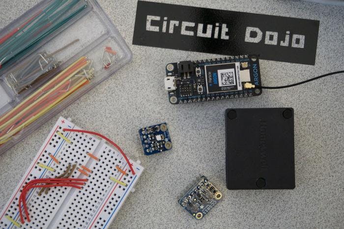
All the parts needed for this project.
The brains of the operation is a Particle Argon. This project is also compatible with any Particle Mesh board and also anything in the Adafruit Feather footprint.
As for the sensors, the most important is the the Honeywell HPM series PM2.5/PM10 sensor. At a high level, it counts how many particles are flying around in your air and gives you a number based on that information. If you ever see air quality data in a weather app like Weather Underground, that information is based off of a particle measurement that the HPM produces.
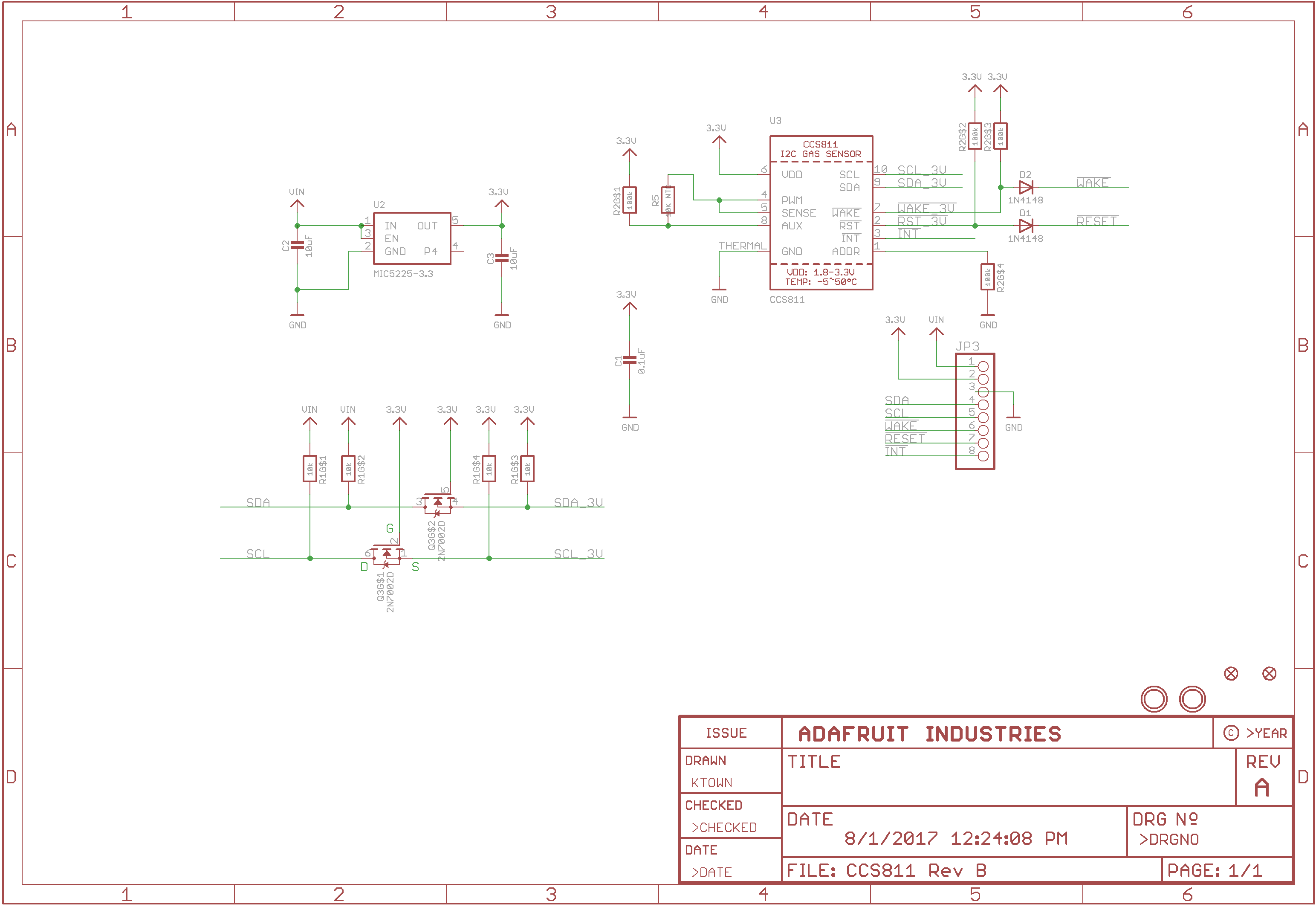
Second, there’s the AMS CCS811. It measures eC02 and TVOCs (total volatile organic compounds). It’s an important data point for indoor air quality. Try placing this sensor in your basement next to your furnace or boiler (if it’s not electric) and you’ll get some surprising readings when it’s running.
Finally, a Silicon Labs Si7021. This little guy has been my go to for combined humidity and temperature readings. It also provides the temperature and C02 readings for the internal calibration of the CCS811.
Fire it up
Here’s the full list of ingredients for this IoT stew:
- Solder-less breadboard hookup wire
- A solder-less breadboard
- A CCS811 breakout board from Adafruit (more details here)
- A Si7021 breakout from Adafruit (more details here)
- A Particle board of your choice.
- A HPMA115 Particle sensor
- Pre assembled Molex cable for the HPMA115 (Molex P/N 0151340803 or similar)
- Some 0.1” pitch headers
I’ve included the Fritzing example with the source for this project. Here’s a screenshot though:
Note: the original Fritzing diagram was incorrect. Both Vin of the CCS811 and Si7021 should be connected to the 3.3V on the Particle. Thanks armor pointing out I goofed 
Particle doesn’t have any Fritizing parts so I had to substitute with an Adafruit Feather. So just close your eyes and pretend we’re using an Argon…
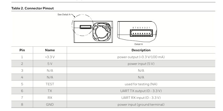
As for the particle sensor, it’s a bit of a mystery how it’s hooked up from that diagram. Here’s the pinout from the data sheet:
HPMA115S0 datasheet
We’re most concerned with the 5V, GND, RX and TX pins.
Just make the connections like so:
- 5V -> USB
- GND -> GND
- RX -> TX (on the Argon)
- TX -> RX (on the Argon).
If you did everything right, your setup will look something like this:
If you’re curious how I hooked up the HPM sensor here were the steps:
-
Cut the pre-assembled cable in half.
-
Remove all the unneeded wires
-
Solder headers to the individual wires
-
Plug em in to the breadboard
Here’s a picture of what the solder job looks like.
Soldering header to wire
I went into further detail on this in the full tutorial.
Setting Up The Firmware
For this project, I’m using Visual Code with the Particle plugins. More on how to set that up here.
TheSi7021(Temperature and Humidity)
The Si7021 is a go-to for humidity and temperature measurements due to its simplicity. The only drawback is that a read to this device, in its simplest form, uses clock stretching.
What does that mean?
Your micro controller is tied up during the time it’s waiting for the temperature and humidity data. For this application, it’s less critical considering we’re taking measurements every minute or two.
Here’s what a typical read looks like:
If you feel like you’re having déjà vu, it’s not surprising. Particle uses the same Wiring/Arudino API that we’re all familiar with.
The CSS811 (TVOCs and C02)
The CCS811 has a few more bells and whistles compared to the Si7021. In particular it has an interrupt pin. An interrupt is particularly useful because you can start a measurement, do some stuff, and then return to it later once it’s done. No blocking code makes for a happy processor.
TheHPM (Particle Sensor)
The HPM sensor unfortunately is not as nice. It uses a UART interface. In my experience UART is a pain to work with especially when you have a tight state machine. I also had trouble writing commands to it over time.
My solution?
Leave it on and running.
By default it sends data every 1 second. All you have to do is be there to listen for it. Over time this does degrade the performance of the fan. Honeywell recommends that it be controlled by a switch to preserve the device life. I ended up doing that in the fully integrated version of this project.
Gotta Get Out
The data is only so useful sitting in the micro controller on your table. You gotta get it out somehow!
I serialized everything together in a JSON blob and sent it as a single publish event. There were a few reasons for this I won’t go into here.
The creation of the blob is straight forward. Take a look below at the actual code:
I simply took each reading and inserted them into a pre-formatted string. I then sent that string using the Particle.publish command.
The cool thing is, the data won’t get sent until all three sensors have finished doing their thing. The one that takes the longest, by far, is the HPM sensor.
Webhook Madness
So we’re pushing data to Particle’s backend. Now what?
After some searching, I found one solution that I’ll share here: GoogleSheets.
Oooh yes. We’re going to directly import the data from this device into Google Sheets.
Here’s the play by play:
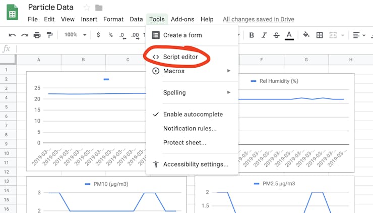
- Go to
Tools->Script Editor. This should pop open a script window.
- Create a new script. And copy the contents of what I’ve written below:
I’ve based the code originally on the post I found on the subject.
- Then I went to
Publish->Deploy as web app - Remember, this app shouldn’t be used by anyone else except you. You can set
Execute the app asand select yourself. - Finally,
Who has access to the appisAnyone, even anonymousotherwise it will require authentication which would not work! If you have already published, you will have to change theProject Versiontonewin order for your changes to apply. - In the Particle console, go to the
Integrationssection and create a newWebhook
- Fill in the name of the event you want to forward. In our case it’s
blob - Enter the URL provided in Step 5
- Make sure the request format is
JSON. You can keep the default JSON format. KeepEnforce SSLenabled. - Make sure the device that you want to watch is defined. In my case I’m using the name that Particle gave my device
hamster_turkey(awesome name, right?) - Go down to the bottom and click
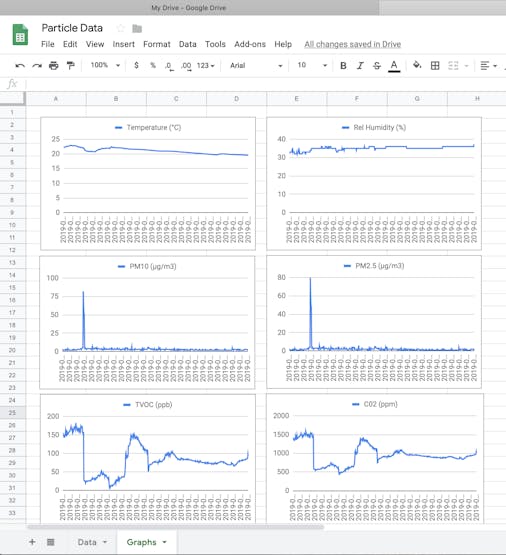
Save - If your Particle is programmed, you should start seeing updated data populate the Google Sheet. You can put data into graphs that update in real time.
Note: This type of data collection isn’t great for large amounts of data spanning more than a few days. It’s great though for short time trials and tests though! I originally was using IFTTT but the data collection was sporadic. Now it’s quite consistent!
You can see my live example here.
We did it!
If you’ve gotten this far. Here’s a virtual high five! 
If you want more, I go into more details on my blog. I cover things like configuring this project for Adafruit’s IoT service, methodology behind the code and more.
Todo
I have a Xenon here that I want to get working with this project. I’m particularly interested in seeing the battery life I can squeeze out of it. Will report back when I get some numbers!
The Source
Oh! I did not forget about the source. Everything for this project and the accompanying breakout board is located on my site here. Go check it out and get started!
