Hi guys ! I finally had time to build my Telephone Isolation Circuit from above. It does work as designed using 2 NPN & 1 PNP Transistor; 1 Dielectric & 1 Ceramic Bi-Polar Capacitor; & 4 Resistors and that’s it.
Here is a video where I use my body resistance to fully turn on an LED but, I need a some help, if you would.
Befoere I hook up my core to this circuit I should I place a load limiting resitor between 3v3 of the core and my circit to protect the core. If so ? what value of resistor should I use ?
AND
DO I need to worry about impediance of Q3 grounding A0 resulting in a lower voltage reading ?
SPECS:
Current flowing to LED at this time is 1.8ma
When the Connector is not being touched the voltage that will be going to A0 is 3v.
When I touch the Connector the voltage that will be going to A0 drops to 1.5 - 1.8v
The scope for this device:
I want to read the value from A0 and trip a Relay connected to the core on D4.
A 50 turn .0025 enable wire will be wrapped around a phone line wire and the 90VAC will trip the Circuit to trip the Relay on D4.
ALSO !!! What else could this sensitivity circuit be used for “A Touch Pad” of some type. Or Touch Buttons ?
The resistor will not provide protection and only limit the current OUT of the 3.3v pin. If you plug a wrong thing to the 3.3V, it's going to fry the core. Only a Diode will protect it.
But with that said, having a diode causes some power loss and you won't need it unless your circuit has stuff which will cause a spike!
The resistor, if you would like to have will act like a fuse. But i figure you won't require it?
@kennethlimcp - Big Thanks. I don’t expect a spike but, if the Dielect Cap or Transistor shorted to ground I was thinking it could take the core with it. I see what bko has to say too about the limit resistor. Its hard to build a 60ma protection in for each pin to protect the core and I’m not an expert on these things so, I will order another core as a back up as I proceed.
I did some testing while I was waiting for your response and this circuit is very cool. I can wave the circuit board up to an electric device and the led goes out. While holding the sensitivity connector I can put my other hand near any power souce and the LED goes out.
Have I build a Bug Dectector too ! More testing is needed for sure.
If anyone wants an idea on how to extend this, just think about CallerID. It is sent as tones down the phone line between rings. It should not be too hard to decode this either via the Spark module, or via an external chip of some sort. And by chip, I don’t mean a CallerID chip, I am talking a small $2 processor (328P or similar).
A lot of work has been done in the Ham Radio world decoding modem tones on such chips, and so interfacing it would not be too hard. You could then have the Spark send a notification direct to your mobile saying who is ringing you. Having done this with a phone modem, I can tell you it is cool!
Alternatively, you can use a Holtek 9032 for the decoding of the CallerID. As a bonus, it also does ring detection. I have just ordered five of the devices from AliExpress for US$10 including postage.
1st Proto-Board for testing and modification. Initial Testing did not produce the same resuls. Will spend next week debugging / changing values of resisors; and use different pickup wire. Then test on phone line to get desired feedback from Ring at 90VAC - Non Contact.
Here is what I have so far but, I have a question ?
I can put the alligator clip on the outside of the telephone line and the Green LED lights up bright.
So I have at least 2 options for this design:
I can use a insulated wrap wire around RING Telephone (Red) wire (adjusting wraps around wire to get proper signal strength) to cause A0 to drop from 3v to 2v. The Core will then Activate D4 and trip a relay to allow the call to come in to my house and ring my phone.
When the phone is answered (Off Hook) the line voltage typically drops from -48vdc to -20v.
I can use an un-insulated clip around both TIP & RING Telephone wires to pickup the On-Hook Voltage of -48vdc causing A0 to go high 3v and the core then will release D4 and opens a relay.
My Question is:
Is it possible to use the unisulated clip to pickup both the DC & AC of the phone line and then split the singal AC <–> DC to 2 cirucits on my board ? If so, what woudl be the best way to do this ?
Okay, to answer my own question I discovered that by placing a Polarized Capacator in my telephone signal it blocks the VDC allowing the 90VAC to pass through.
Now that I know how to inductively pickup both VDC & VAC from a phone line I need to incorpoarte the Relay Circuit.
@kennethlimcp, I know you can’t sleep tonight (your time) now that you and @will have got the files for your “SUPER AWESOME” MicroSD/ Fram Shield off to the FAB !
Would you take a look at the below schematic from @cjenkins Advance Relay Shield and see if using SMD there would be enough room to combine my above circuit and Carlos Advance Relay Circuit on a 1" x 3" PCB ? (Would most likely want to use a low current 120vac micro relay or will have to use Opto coupler protection from phone line 90vac)
Detection Method - Non-Contact of Telephone Line Current & Voltage both -48VDC & 90VAC. The circuit I am using is inductive sense of voltage that cause Q3 to saturate.
Purpose of Project - Isolation of house phone wires from the GRID until a call actually is sent from the phone company central office.
When the phone is “ON HOOK” (not in use) the voltage is steady -48VDC (USA)
When a call is placed a ring voltage of 90VAC becomes present ON/OFF/ON until answered.
When a phone is answered the Voltage drops to -20VAC (USA)
I want my project to keep a relay open as long as -48VDC is detected by induction and this will keep my home phone wires disconnected from the grid until a call is place to my home.
As a call is coming to my home the 90VAC associated with it needs to be detected separagely from the VDC so VDC needs to be filtered out form VAC and when VAC is detected the Relay will be closed and allow the call to ring my phones.
When I pick up the call the phone line voltage goes “OFF HOOK” and down to -20VDC and the relay will remain open unitil the phone is hanged up and return to “ON HOOK” which will close the relay and complete the cycle once again returning my home to “OFF THE PHONE LINE GRID”.
Is there another way to detect both VDC and VAC without physical contact of phone line wire other than EMF Detection (voltage present) ? (Not sure how parameter voltage - non contact - voltage tests work that do the same thing).
You help is greatly appreciated and if what I want to do can be accomplished, I think it could be a great shield but, may not be as popular or useful as your MicoSD Card / Fram shield.
With my little little electrical knowledge after 3 years of studies, DC is constant the electric.magnetic fields are not changing. A non-invasive detection technique is not possible.
AC is fine.
Seems like you have got something working and i'm not going to change anything for now.
@spydrop, @kennethlimcp, for the AC part you can use a full-wave bridge and drive an opto-isolator whose output will be a logic level that you can read. DC will not make it through the full wave bridge so for that, you will need something else.
DC cannot be detected by induction since inductive pickup requires a changing magnetic field. However, a non-invasive hall-effect sensor will pickup the static magnetic field induced by the DC current. Here is an example of a DC sensor breakout. You pick a sensor based on the amount of current you expect to sense so you may have to experiment to measure the -48VDC vs -20VDC current levels in order to pick the right sensor.
You may also want to take a look at this for some ideas on the ring part.
@kennethlimcp and @peekay123 you guys are my hero. I struggle so much with electronics and coding but, your comments have once again pointed me in the right direction. Your comments – I value so much and THANK YOU !
@peekay123, I have worked on hall effect sensors on Currie Bicycle Motors in the past but, did not know exactly how they work. Now, thanks to you, I have a better understanding and can move forward with much less frustration.
The phone line when OFF HOOK (call answered) the current draw will be between normaily 35mA and 70ma with a minum of 20ma bottom limit provided by Telco Central Office.
??? Can I use the above linked Spark Fun 5A Hall Effect breakout or do I need one that is designed for less “mA” current ?
@spydrop, I figured you might ask that The ACS712 can be used with an amplifier to give you more sensitivity. Sparkfun has this breakout that does exactly that. It lets you adjust the gain and the offset of the output (normally at 1/2 Vcc). The only catch is that the module requires 5V so you will have to adjust the gain and offset so as not to exceed the 3.3V maximum analog input limit on the Spark.
I’m glad to see you are pre-emting the obvious direction I will take; once only thought possible by the gods of the Greeks Okay, I seriously say “WOW” ! I think I can do exactly what you suggest. Your 2 comments here will keep me busy all weekend; Highly Motivated now !
The ACS712 is only capable of providing reliable current detection at 166mA or above based on the Datasheet and reading some of the comments at the Spark Fun product page. I need 20mA - 70mA detection. This breakout board requires a physical connect to the phone line but, I can’t do that.
To keep from having an FCC license to hook this to a Phone line I need to be able to detect DC present and I think I am doing this already. Let me explain a little more in detail
**
AM I DETECTING DC with my board above ?
**
On my completed board above there is a Red wire and Black Wire with alligator clips. The Red wire is the only wire with a physical connection to the board.
I can take the Alligator clip on the Red wire and hook it to a vinyl jacketed phone line extension wire and it excites Q3 NPN Transistor and the GREEN LED lights with 3 volts without any VAC Being present.
I can do a vidoe tonight of how I can pickup the -48VDC with the Red Aligator Clip Connected and post it if that would help.
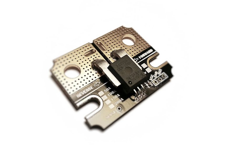
@peekay123, Sorry to be a pain and just when you have time. What about this current sensor ACS-758 ? One version can do much lower than Spark Funs model:
Details
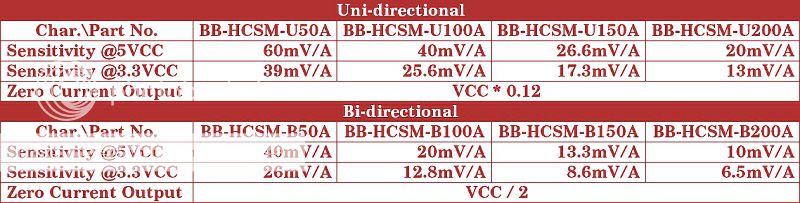
Sensor Type: Allegro ACS758 Series Hall Current Sensor.Support Voltage (VCC): 3.0 ~ 5.5VDC.Output Signal (OUT): Analog Output.Ultra-low Power Loss: 100 μΩ Internal Conductor Resistance.Copper Thickness: 4 oz. (see blow slection table for more specs)
Well shiver me timbers! I missed that one didn’t I
After reviewing the specs, none of the Allegro sensors will work at the low currents you are trying to sense. The only way you can reliably measure a low DC current is by measuring the voltage drop across a resistor. This “current sense” resistor is typically very small (1 milliohm or less). Unfortunately, this method is “invasive”.
Another approach to get off hook detection is outlined here. This circuit uses an opto-isolator for line isolation and the output would be pulled up to 5V instead of the 12V indicated.

 off to the FAB !

 Okay, I seriously say “WOW” ! I think I can do exactly what you suggest. Your 2 comments here will keep me busy all weekend; Highly Motivated now !