This appears to be possible using the STM32 one pulse mode.
Updates to this will be on Github.
While I assume you know what you’re doing, I’ve included some additional warnings because this can be very dangerous if you don’t know what you’re doing. That’s for everyone who finds this post by search.
Photon Dimmer Example
Example code for implementing a pulse width modulation dimmer on the Photon
Note: Working with high voltages is extremely dangerous. There is a high risk of electrocuting someone or starting a fire. Do not ask me how to wire up the zero-crossing detector and triac. I will ignore your request, as if you don’t know that, you should not be messing with high voltages.
When implementing a dimmer, you normally have two things:
- A zero-crossing detector
- A triac to control the load
The way the dimmer works is that you wait an amount of time after zero-crossing, then turn on the triac. The triac turns itself off when the alternating current next reaches zero.

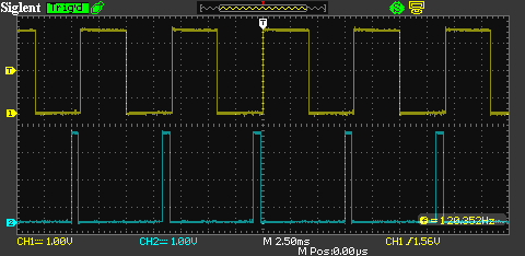
The simulated zero-crossing detector is the top channel (yellow). The rising edge A marks a zero crossing. The next rising edge marks the next zero crossing. The frequency is 120 Hz., simulating both the upper and lower halves of a 60 Hz signal.
The dimmed signal is on the bottom channel (blue). B is the programmed phase delay from A. The light would turn on here. C is where the triac is turned off. It must be turned off before the next zero-crossing.
Here are waveforms for dim (mostly off):
Medium or half bright:
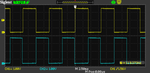
Bright, almost completely on:

While you could do this using software interrupts, things like interrupt latency can cause issues. The technique here does it entirely with hardware timers.
Note: This is extremely experimental. It may not work and relies on directly accessing hardware on the STM32F205 and may break in the future.
The test circuit
In the test circuit:
- A potentiometer is connected to 3V3 and GND on the outside terminals and A0 on the center terminal. This is the brightness control.
- D3 is the variable pulse output. This would go to the triac.
- D2 is the zero-crossing detector. The rising edge of this signal indicates zero-crossing.
Instead of actually using a zero-crossing detector, I just simulated it here with a 120 Hz square wave.
The code
The code should be relatively straightforward. There are a lot of comments, so just read those.
#include "Particle.h"

// Example program for implementing a triac-based dimmer type circuit on the Photon

TIM_TypeDef* TIMx;
GPIO_InitTypeDef GPIO_InitStructure;
TIM_TimeBaseInitTypeDef TIM_TimeBaseStructure;
TIM_OCInitTypeDef  TIM_OCInitStructure;
TIM_ICInitTypeDef  TIM_ICInitStructure;

void setup() {
	Serial.begin(9600);


	// This example uses pins D3 and D4. You can only used pins connected to timers.
	// You need to pick a timer with two available channels as well.
	// https://docs.particle.io/datasheets/photon-(wifi)/photon-datasheet/#pinout-diagrams
	// D3 = PB4 = TIM3_CH1 <- variable pulse output
	// D2 = PB5 = TIM3_CH2 <- zero-crossing trigger pulse (rising = zero cross)

	RCC_APB1PeriphClockCmd(RCC_APB1Periph_TIM3, ENABLE);

	// Set up the pin modes for the two pins D2 (PB4) and D3 (PB5)
	GPIO_InitStructure.GPIO_Pin =  GPIO_Pin_4 | GPIO_Pin_5;
	GPIO_InitStructure.GPIO_Mode = GPIO_Mode_AF;
	GPIO_InitStructure.GPIO_OType = GPIO_OType_PP;
	GPIO_InitStructure.GPIO_PuPd  = GPIO_PuPd_UP;
	GPIO_InitStructure.GPIO_Speed = GPIO_Speed_25MHz;
	GPIO_Init(GPIOB, &GPIO_InitStructure);

	// Connect D2 and D3 (PB4 and PB4) to GPIO_AF_TIM3
	GPIO_Init(GPIOB, &GPIO_InitStructure);
	GPIO_PinAFConfig(GPIOB, GPIO_PinSource4, GPIO_AF_TIM3);
	GPIO_PinAFConfig(GPIOB, GPIO_PinSource5, GPIO_AF_TIM3);

	// Since we selected D2 and T3, we'll be working with TIM3. Note: If you change timers
	// there are multiple things that need to be changed, not just this.
	TIMx = TIM3;

	// Based on this sample code:
	// https://github.com/bjornfor/stm32-test/tree/master/STM32L1xx_StdPeriph_Lib_V1.1.1/Project/STM32L1xx_StdPeriph_Examples/TIM/OnePulse

	// Set a 4 MHz timer clock
	uint32_t SystemCoreClock = 60000000UL;
	uint16_t PrescalerValue = (uint16_t) (SystemCoreClock / 4000000) - 1;

	// The zero-crossing synchronization signal is 120 Hz (half of a 60 Hz signal)
	// With a 4 MHz timer clock, one cycle of 120 Hz is 33,333 clocks (after prescaling)
	// TIM_Period is the distances in clocks to where the signal will drop to LOW again
	// If you want the signal to drop lower faster, make TIM_Period smaller than 32500, but
	// this will make it impossible to set very low dim values.
	TIM_TimeBaseStructure.TIM_Period = 32500; // pulse width (maximum)
	TIM_TimeBaseStructure.TIM_Prescaler = PrescalerValue;
	TIM_TimeBaseStructure.TIM_ClockDivision = TIM_CKD_DIV1;
	TIM_TimeBaseStructure.TIM_CounterMode = TIM_CounterMode_Up;
	TIM_TimeBaseStructure.TIM_RepetitionCounter = 0;
	TIM_TimeBaseInit(TIMx, &TIM_TimeBaseStructure);

	// This sets the output mode for the one pulse mode output
	// TIM3 PWM2 Mode configuration: Channel1
	// TIM_Pulse is set to 1000 here, but it's overrridden in loop()
	// If you wanted to reverse the polarity so you could drive the low side
	// of an opto-coupler or MOSFET, switch TIM_OCPolarity here.
	TIM_OCInitStructure.TIM_OCMode = TIM_OCMode_PWM2;
	TIM_OCInitStructure.TIM_OutputState = TIM_OutputState_Enable;
	TIM_OCInitStructure.TIM_Pulse = 1000; // delay
	TIM_OCInitStructure.TIM_OCPolarity = TIM_OCPolarity_High;
	TIM_OC1Init(TIM3, &TIM_OCInitStructure);

	// This sets the input mode for the zero-crossing detector
	// If you wanted to make this work on falling, for example, change TIM_ICPolarity.
	// TIM3 configuration in Input Capture Mode
	TIM_ICStructInit(&TIM_ICInitStructure);
	TIM_ICInitStructure.TIM_Channel = TIM_Channel_2;
	TIM_ICInitStructure.TIM_ICPolarity = TIM_ICPolarity_Rising;
	TIM_ICInitStructure.TIM_ICSelection = TIM_ICSelection_DirectTI;
	TIM_ICInitStructure.TIM_ICPrescaler = TIM_ICPSC_DIV1;
	TIM_ICInitStructure.TIM_ICFilter = 0;
	TIM_ICInit(TIM3, &TIM_ICInitStructure);

	// One Pulse Mode selection
	TIM_SelectOnePulseMode(TIM3, TIM_OPMode_Single);

	// Input Trigger selection
	TIM_SelectInputTrigger(TIM3, TIM_TS_TI2FP2);

	// Slave Mode selection: Trigger Mode
	TIM_SelectSlaveMode(TIM3, TIM_SlaveMode_Trigger);

	TIM_Cmd(TIMx, ENABLE);
}

void loop() {
	// We use a potentiometer (center tap = A0, outer to 3V3 and GND) to adjust the pulse delay
	// The delay should be 0 - around 33290 or so so scale the 0-4095 from the ADC by multiplying by 8
	TIM_SetCompare1(TIMx, analogRead(A0) * 8);
}
Other resources
