Hello!!
After testing the TFT, now I am trying to connect using the same pins, the TFT. Have I to connect them on different pins? If it is affirmative, what is the schema?
Thanks a lot!!!
Alberto
Hello!!
After testing the TFT, now I am trying to connect using the same pins, the TFT. Have I to connect them on different pins? If it is affirmative, what is the schema?
Thanks a lot!!!
Alberto
I don’t quite understand the question, but if you want to connect the SD card or another SPI device you can use the MOSI, MISO and CLK pins to all devices in parallel, only the CS/SS pin has to be seperate and exclusivly active for each device.
But since the SS (A2) pin always goes active whenever SPI communication happens, you can only use this pin if this device is the one and only device on the hardware SPI port.
Alternatively you could use one device on the hardware SPI pins and one or some other device(s) with softSPI on different pins - but this seems like a waste of pins.
Hi @ScruffR!
Yes, I am using this type of screen: http://goo.gl/6QTokm4, so as you can see, it has different pins for SD card and screen. I was thinking, as you said, that MISO, MOSI and CLK are the same pins, but I had doubts about the CS pin; so how can I emulate the softSPI ?
Thanks!
@albertuslm, since I can’t view the link you have given, I’m not sure, but I have a TFT display with SD and two sets of SPI headers on it too, and on my board the SPI headers are actually directly connected to eachother - apart from the respective CS pins.
So just have a test if this is the case for your board too. A cheapo continuity tester should do for that.
Otherwise you can find the SoftSPI as part of @BDub 's LiquidCrystal library
@ScruffR, @albertuslm there seems to be some confusion regarding the use of A2 (SS) as the slave select line for hardware SPI.
This is a common misconception and not quite correct. The SPI.begin() call allows for a slave select pin to be specified and if not, it will default to pin A2. However, all the SPI call does is set the SS pin as an output and sets it high:
pinMode(ss_pin, OUTPUT);
digitalWrite(ss_pin, HIGH);
Furthermore, the Core firmware sets the SS mode to "soft", meaning it must be controlled in software and not by hardware:
SPI_InitStructure.SPI_NSS = SPI_NSS_Soft;
The user app or a device library needs to control the SS (A2) or any other pin used as a slave select as the STM32 SPI controller does not manage this pin. The thing to remember is that SPI.begin() will ALWAYS set A2 to a high output UNLESS you specify a different slave select pin.
So, the short of it is that you can use A2 or any other pin as a slave select. Most libraries that use hardware SPI will require that you specify the CS (chip select aka slave select) pin as part of the call to the constructor. For example, for the SSD1351 based displays:
Adafruit_SSD1351 tft = Adafruit_SSD1351(cs, dc, rst);

cs specifies the chip select (slave select) pin
So you can have two or more hardware SPI devices as long as you have two or more different slave select pins. The exception to this rule is where the SPI devices require different SPI modes (SPI.setDataMode). This was found to be the problem when using a Digole display and an SD card together for example. For these to operate correctly, one device has to be driven using software SPI while the other can use hardware SPI. Oddly, they can use the same MOSI/MISO/SCK lines since each SPI operation is mutually exclusive unless they are done within an interrupts service routine. In that case, the software SPI lines must be on different pins. ![]()
Thanks @peekay123 for this clarification.
I should have checked this beforehand, but I always assumed that SS was doing its thing but it could just be substituted by any other.
Good to know now how it really is and thanks for the detailed background info 
Thanks @peekay123!! as you might know, I was working with this tft: http://www.dx.com/en/p/2-2-serial-spi-tft-color-lcd-module-for-arduino-red-silver-234675#.VJGaR4rF8Q5, we were speaking about that in this thread: http://community.spark.io/t/solved-problem-with-spark-core-tft-2-2-w-sd/8832. Right now I have working the tft, but I want to work with the SD card also to show on the tft images. Please, could you help me?
What is the library I have to use for getting files from SD card? I tried with one that you have on github: https://github.com/technobly/SparkCore-SD, but I got several errors when I tried to compile it with the Spark Dev.
Please, could you tell me what are the steps to install the library and use it?
Again, thanks a lot, you are saving me!!
Alberto
@albertuslm, I have the display and it’s working fine with the Spark. I will hook up the SD and test the library with it. I think there may be issues with the IDE library so I will be using CLI or DEV for testing. I should be able to get to this in the next couple of days 
UPDATE: I have the ILI9341/mfGFX/SD code compiling on CLI and I will do the wiring and testing tonight
@albertuslm, I got the ili9341 2.2" display working with mfGFX, SD and pulling in a BMP file (purple.bmp) from the SD card do display. I put all the files in a single directory and compiled/flashed using Spark CLI. I put the files in dropbox here, including the bmp file.
Format (fat16 or fat32) an SD card and copy purple.bmp to it. Don’t leave the bmp file in the same directory as the code or CLI will try and compile it! Make sure you change these line in tftSDbitmap.ino to reflect your wiring:
#define TFT_DC D5
#define TFT_CS D4

#define SD_CS D7
Let me know how it goes!
HI @peekay123! sorry for the delay, I was not at home last days to test it. Doing it right now.
Again, thanks for your help!
Last question, have I to connect wires in the sd part or using the tft ones?
@albertuslm, you need to wire the SD side. 
@peekay, thanks again for the tip, it works!!! and works really amazing!!! thanks again!
@peekay123, I tried your code and it works, but some strange error occours:
after uploading the Firmware the SD-Card is not accessible, the program Returns ‘failed’, same result after resetting the CORE. If i pull out the USB-cable or take the 3v3 power supply from the Display and reconnect it the SD Card works like Magic and the Image is loaded and displayed. I am not sure where the Problem is, maybe the SD instance is still open…
I am on Windows 7 with Particle Dev.
My Connections are as follows:
#define TFT_DC  D5
#define TFT_CS  D4
#define TFT_RST A0
#define SD_CS D7

Adafruit_ILI9341 tft = Adafruit_ILI9341(TFT_CS, TFT_DC, TFT_RST);

// TFT			-----	CORE
// SDO/MISO	        -----	A4
// LED			-----	to Vin via 220ohm resistor
// SCK			-----	A3
// SDI/MOSI	        -----	A5
// DC/RS		-----	A1
// RESET		-----	A0
// TFT_CS		-----	A2
// GND			-----	GND
// Vcc			-----	Vin
//
// SD_CS		----- D7
// SD_MOSI	        ----- A5 // same as SDI/MOSI
// SD_MISO	        ----- A4 // same as SDO/MISO
// SD_SCK		----- A3 // same as SCK
If I understand correctly, when you remove the power from the display and then reapply it (and I assume reset the Core as well), everything works as expected? This effectively resets the display. The original demo program specifified the TFT_RST line as zero or none. This was done because there seemed to be problems with the software driven reset. This explains why resetting the power to the display fixes the issue. Go back to the original no TFT_RST code and try again. At some point I'll have to look at the ILI9341 reset specs to see what the issue might be. ![]()
@peekay123: I tried again the behviour of the CORE:
changed back to Adafruit_ILI9341 tft = Adafruit_ILI9341(TFT_CS, TFT_DC, 0);
after uploading new Firmware SD fails
after resetting SD fails
anfter disconnecting the TFTs power SD fails
after unplugging CORE and plugging back SD works and Displays the Image - strange…
@jmF, it sounds like a reset/initialization issue. Which LCD are you using? I checked the timing of the RST in the ILI9341 code and it seems ok.
@peekay123, ist this Board
with the additional F_CS pin for the prepared Flash chip
@peekay123, I just tried your original sketch with my CORE, and got the same behaviour… 
@jmF, what is "prepared Flash chip". This is not shown on the product link.
@peekay123, my apologies for answering delayed. Weekend started with an accident for me…
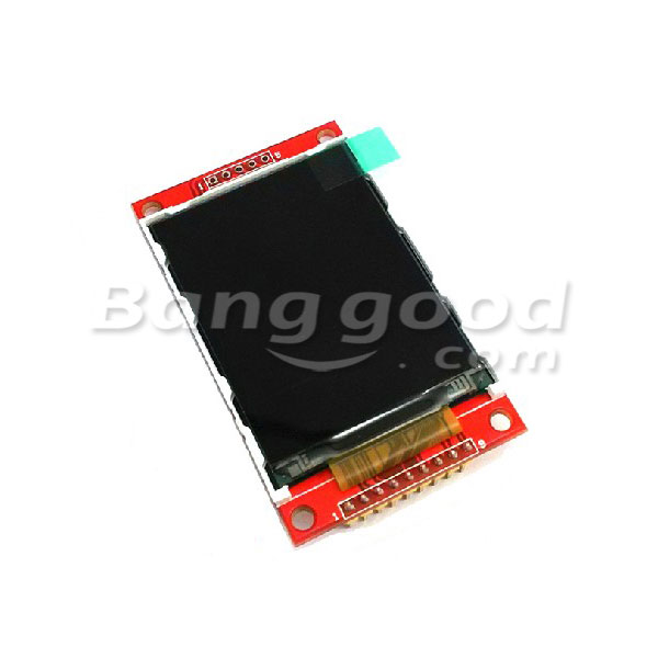
The display i use has on the SD side 5 connectors instead of 4 (see banggood article img). This pin seems to be CS for some flash memory that can be soldered on the board.
It seems there are different versions of this display module with different functionalities.
After all, the SD card still shows this strange behaviour with me - after disconnecting power the SD card works, after reset not.