I have a Photon with an official Shield Shield, and then a generic sensor shield on that with I2C pins.
I have used the “included” LiquidCrystal I2C libraries, connected up the LCD 1602 as per diagrams and works absolutely perfectly. This is a little bulky and a waste for my simple need. I also know that the LCD works and that my code is correct… so all is well.
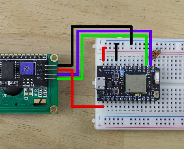
I am trying to get it all working WITHOUT the Shield Shield and Sensor Shield. I am using the same code as before, and using the wiring diagrams as per this:
However, I am getting just BLOCKS instead of any characters. Also, using 4.7K resistors.
I have also used an I2C scanner (as advised from another thread) and the device is reporting “no I2C devices”, therefore, I am thinking that I am missing something pretty fundamental in the wiring…
Any ideas? Seems a waste to have a Shield Shield and Sensor Shield to run a simple LCD!!!
then the problem is that the display requires 5V. The 3V3 pin on the Photon is only 3.3V.
Assuming you’re powering by USB, you can probably connect the VCC pin on the display to VIN. Also connect the pull-up resistors to VIN, not 3V3. The I2C pins of the Photon are 5V tolerant, so this will work fine without the shield shield.
I have also tried powering from VIN (with the appropriate resistors) too. Both from USB into my PC and proper wall socket. Everything powers up nicely, but the characters are all blocks and nothing shows on the scanner.
The 1602 LCD I have working fine (with Shield) is the following:
@brixo, can you please review how everything is connected again? Can you take a picture of it working WITH the shield shield and then how you have it wired without it?
All documentation shows SCL > D0 and SDA > D1 - however, randomly, by accident, I swapped them over and everything comes to life. Unless I’ve read poor documentation or my particular device isn’t labelled correctly - this is a mystery.
That’s very odd, since that was the first thing I checked when I looked at your first image in your first post and there you had it correct (beware of the parallax error tho’)


 (beware of the parallax error tho’)