Here’s some example code to do that. What it does is use hardware ADC1 and ADC2 to sample two different signals at exactly the same time. It also uses a hardware timer and DMA to sample the data continuously. The example program samples the values 1000 times per second but to avoid overflowing the serial port, takes the mean of each group of 100 samples and prints that to serial. You could do other things like find the max for short current spikes, even do an RMS calculation for AC signals, if you wanted to.
#include "Particle.h"
//
// ADCDMA - Class to use Photon ADC in DMA Multi Mode
//
#include "adc_hal.h"
#include "gpio_hal.h"
#include "pinmap_hal.h"
#include "pinmap_impl.h"
// This is actually 60 (well, 59) to divide the 60 MHz system clock down to 1 MHz
// via the prescaler. Since we use TIM3, the timer is a 16-bit timer so this allows
// the sampling rate to go a little lower.
const uint16_t TIM_PRESCALER = (uint16_t)(60000000UL / 1000000UL) - 1;
// This is how fast to sample the ADC in Hz. The minimum is about 15 Hz unless
// you adjust the TIM_PRESCALER, then you can go lower.
const uint32_t SAMPLING_FREQ_HZ = 1000UL;
// This is the timer period passed to the hardware; it needs to be 0 - 65535.
// The 1000000UL constant is the frequency the prescaler scales to.
const uint16_t TIM_PERIOD = (uint16_t) (1000000UL / SAMPLING_FREQ_HZ) - 1;
// The sample buf is uint16_t samples. Two samples are taken each time the timer fires
// (SAMPLING_FREQ_HZ), one from each ADC. A double buffering system is used, so samples
// are buffered up using DMA then a flag is triggered for the buffer to be handled from
// loop. You want to buffer to be twice the number of samples you want to handle at each
// processing.
//
// For example, I wanted to output data 10 times per second so the serial port wouldn't
// overflow. Since we're sampling 1000 times per second, I would average 100 samples and
// display the average. So the buffer needs to be 400 samples long.
const size_t SAMPLE_BUF_SIZE = 400;
// These are the two pins to sample
const int SAMPLE_PIN_1 = A0;
const int SAMPLE_PIN_2 = A1;
uint16_t samples[SAMPLE_BUF_SIZE];
//
//
//
class ADCDMA {
public:
ADCDMA(int pin1, int pin2, uint16_t *buf, size_t bufSize);
virtual ~ADCDMA();
void start(size_t freqHZ);
void stop();
private:
int pin1;
int pin2;
uint16_t *buf;
size_t bufSize;
};
// Helpful post:
// https://my.st.com/public/STe2ecommunities/mcu/Lists/cortex_mx_stm32/Flat.aspx?RootFolder=https%3a%2f%2fmy%2est%2ecom%2fpublic%2fSTe2ecommunities%2fmcu%2fLists%2fcortex%5fmx%5fstm32%2fstm32f207%20ADC%2bTIMER%2bDMA%20%20Poor%20Peripheral%20Library%20Examples&FolderCTID=0x01200200770978C69A1141439FE559EB459D7580009C4E14902C3CDE46A77F0FFD06506F5B¤tviews=6249
ADCDMA::ADCDMA(int pin1, int pin2, uint16_t *buf, size_t bufSize) : pin1(pin1), pin2(pin2), buf(buf), bufSize(bufSize) {
}
ADCDMA::~ADCDMA() {
}
void ADCDMA::start(size_t freqHZ) {
// Using Dual ADC Regular Simultaneous DMA Mode 1
// Using Timer3. To change timers, make sure you edit all of:
// RCC_APB1Periph_TIM3, TIM3, ADC_ExternalTrigConv_T3_TRGO
RCC_AHB1PeriphClockCmd(RCC_AHB1Periph_DMA2, ENABLE);
RCC_APB2PeriphClockCmd(RCC_APB2Periph_ADC1, ENABLE);
RCC_APB2PeriphClockCmd(RCC_APB2Periph_ADC2, ENABLE);
RCC_APB1PeriphClockCmd(RCC_APB1Periph_TIM3, ENABLE);
// Set the pin as analog input
// GPIO_InitStructure.GPIO_Mode = GPIO_Mode_AN;
// GPIO_InitStructure.GPIO_PuPd = GPIO_PuPd_NOPULL;
HAL_Pin_Mode(pin1, AN_INPUT);
HAL_Pin_Mode(pin2, AN_INPUT);
// Enable the DMA Stream IRQ Channel
NVIC_InitTypeDef NVIC_InitStructure;
NVIC_InitStructure.NVIC_IRQChannel = DMA2_Stream0_IRQn;
NVIC_InitStructure.NVIC_IRQChannelPreemptionPriority = 0;
NVIC_InitStructure.NVIC_IRQChannelSubPriority = 0;
NVIC_InitStructure.NVIC_IRQChannelCmd = ENABLE;
NVIC_Init(&NVIC_InitStructure);
TIM_TimeBaseInitTypeDef TIM_TimeBaseStructure;
TIM_TimeBaseStructInit(&TIM_TimeBaseStructure);
TIM_TimeBaseStructure.TIM_Period = TIM_PERIOD; // constant defined at the top of this file
TIM_TimeBaseStructure.TIM_Prescaler = TIM_PRESCALER; // constant defined at the top of this file
TIM_TimeBaseStructure.TIM_ClockDivision = 0;
TIM_TimeBaseStructure.TIM_CounterMode = TIM_CounterMode_Up;
TIM_TimeBaseInit(TIM3, &TIM_TimeBaseStructure);
TIM_SelectOutputTrigger(TIM3, TIM_TRGOSource_Update); // ADC_ExternalTrigConv_T3_TRGO
TIM_Cmd(TIM3, ENABLE);
ADC_CommonInitTypeDef ADC_CommonInitStructure;
ADC_InitTypeDef ADC_InitStructure;
DMA_InitTypeDef DMA_InitStructure;
// DMA2 Stream0 channel0 configuration
DMA_InitStructure.DMA_Channel = DMA_Channel_0;
DMA_InitStructure.DMA_Memory0BaseAddr = (uint32_t)buf;
DMA_InitStructure.DMA_PeripheralBaseAddr = 0x40012308; // CDR_ADDRESS; Packed ADC1, ADC2;
DMA_InitStructure.DMA_DIR = DMA_DIR_PeripheralToMemory;
DMA_InitStructure.DMA_BufferSize = bufSize;
DMA_InitStructure.DMA_PeripheralInc = DMA_PeripheralInc_Disable;
DMA_InitStructure.DMA_MemoryInc = DMA_MemoryInc_Enable;
DMA_InitStructure.DMA_PeripheralDataSize = DMA_PeripheralDataSize_HalfWord;
DMA_InitStructure.DMA_MemoryDataSize = DMA_MemoryDataSize_HalfWord;
DMA_InitStructure.DMA_Mode = DMA_Mode_Circular;
DMA_InitStructure.DMA_Priority = DMA_Priority_High;
DMA_InitStructure.DMA_FIFOMode = DMA_FIFOMode_Enable;
DMA_InitStructure.DMA_FIFOThreshold = DMA_FIFOThreshold_HalfFull;
DMA_InitStructure.DMA_MemoryBurst = DMA_MemoryBurst_Single;
DMA_InitStructure.DMA_PeripheralBurst = DMA_PeripheralBurst_Single;
DMA_Init(DMA2_Stream0, &DMA_InitStructure);
// Don't enable DMA Stream Half / Transfer Complete interrupt
// Since we want to write out of loop anyway, there's no real advantage to using the interrupt, and as
// far as I can tell, you can't set the interrupt handler for DMA2_Stream0 without modifying
// system firmware because there's no built-in handler for it.
// DMA_ITConfig(DMA2_Stream0, DMA_IT_TC | DMA_IT_HT, ENABLE);
DMA_Cmd(DMA2_Stream0, ENABLE);
// ADC Common Init
ADC_CommonInitStructure.ADC_Mode = ADC_DualMode_RegSimult;
ADC_CommonInitStructure.ADC_Prescaler = ADC_Prescaler_Div2;
ADC_CommonInitStructure.ADC_DMAAccessMode = ADC_DMAAccessMode_1;
ADC_CommonInitStructure.ADC_TwoSamplingDelay = ADC_TwoSamplingDelay_5Cycles;
ADC_CommonInit(&ADC_CommonInitStructure);
// ADC1 configuration
ADC_InitStructure.ADC_Resolution = ADC_Resolution_12b;
ADC_InitStructure.ADC_ScanConvMode = DISABLE;
ADC_InitStructure.ADC_ContinuousConvMode = DISABLE;
ADC_InitStructure.ADC_ExternalTrigConvEdge = ADC_ExternalTrigConvEdge_Rising;
ADC_InitStructure.ADC_ExternalTrigConv = ADC_ExternalTrigConv_T3_TRGO;
ADC_InitStructure.ADC_DataAlign = ADC_DataAlign_Right;
ADC_InitStructure.ADC_NbrOfConversion = 1;
ADC_Init(ADC1, &ADC_InitStructure);
// ADC2 configuration - same
ADC_Init(ADC2, &ADC_InitStructure);
//
ADC_RegularChannelConfig(ADC1, PIN_MAP[pin1].adc_channel, 1, ADC_SampleTime_15Cycles);
ADC_RegularChannelConfig(ADC2, PIN_MAP[pin2].adc_channel, 1, ADC_SampleTime_15Cycles);
// Enable DMA request after last transfer (Multi-ADC mode)
ADC_MultiModeDMARequestAfterLastTransferCmd(ENABLE);
// Enable ADCs
ADC_Cmd(ADC1, ENABLE);
ADC_Cmd(ADC2, ENABLE);
ADC_SoftwareStartConv(ADC1);
}
void ADCDMA::stop() {
// Stop the ADC
ADC_Cmd(ADC1, DISABLE);
ADC_Cmd(ADC2, DISABLE);
DMA_Cmd(DMA2_Stream0, DISABLE);
// Stop the timer
TIM_Cmd(TIM3, DISABLE);
}
ADCDMA adcDMA(SAMPLE_PIN_1, SAMPLE_PIN_2, samples, SAMPLE_BUF_SIZE);
// End ADCDMA
void setup() {
Serial.begin(9600);
adcDMA.start(SAMPLING_FREQ_HZ);
}
void loop() {
uint16_t *samplesToProcess = NULL;
if (DMA_GetFlagStatus(DMA2_Stream0, DMA_FLAG_HTIF0)) {
DMA_ClearFlag(DMA2_Stream0, DMA_FLAG_HTIF0);
samplesToProcess = samples;
}
if (DMA_GetFlagStatus(DMA2_Stream0, DMA_FLAG_TCIF0)) {
DMA_ClearFlag(DMA2_Stream0, DMA_FLAG_TCIF0);
samplesToProcess = &samples[SAMPLE_BUF_SIZE / 2];
}
if (samplesToProcess != NULL) {
// There is a sample buffer to process. Because we only can write out samples so fast
// over serial, we just print the mean of 100 samples here. This would also be good
// place to check for min, max, median, whatever you wanted to, if you wanted to find
// out more info about your signal. Or you could even calculate RMS here, for AC signals.
uint32_t sum1 = 0;
uint32_t sum2 = 0;
for(size_t ii = 0; ii < SAMPLE_BUF_SIZE / 2;) {
sum1 += samplesToProcess[ii++];
sum2 += samplesToProcess[ii++];
}
uint32_t avg1 = sum1 / (SAMPLE_BUF_SIZE / 4);
uint32_t avg2 = sum2 / (SAMPLE_BUF_SIZE / 4);
Serial.printlnf("%d,%d", avg1, avg2);
}
}
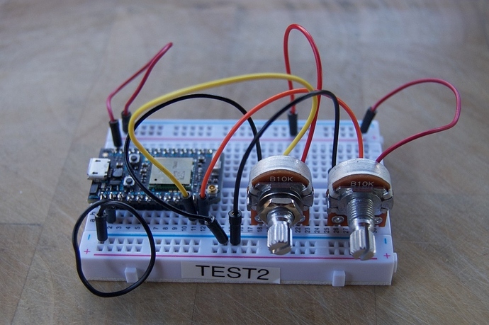
I tested it with this potentiometer setup, but obviously it would work with any pair of analog inputs.
![]()

