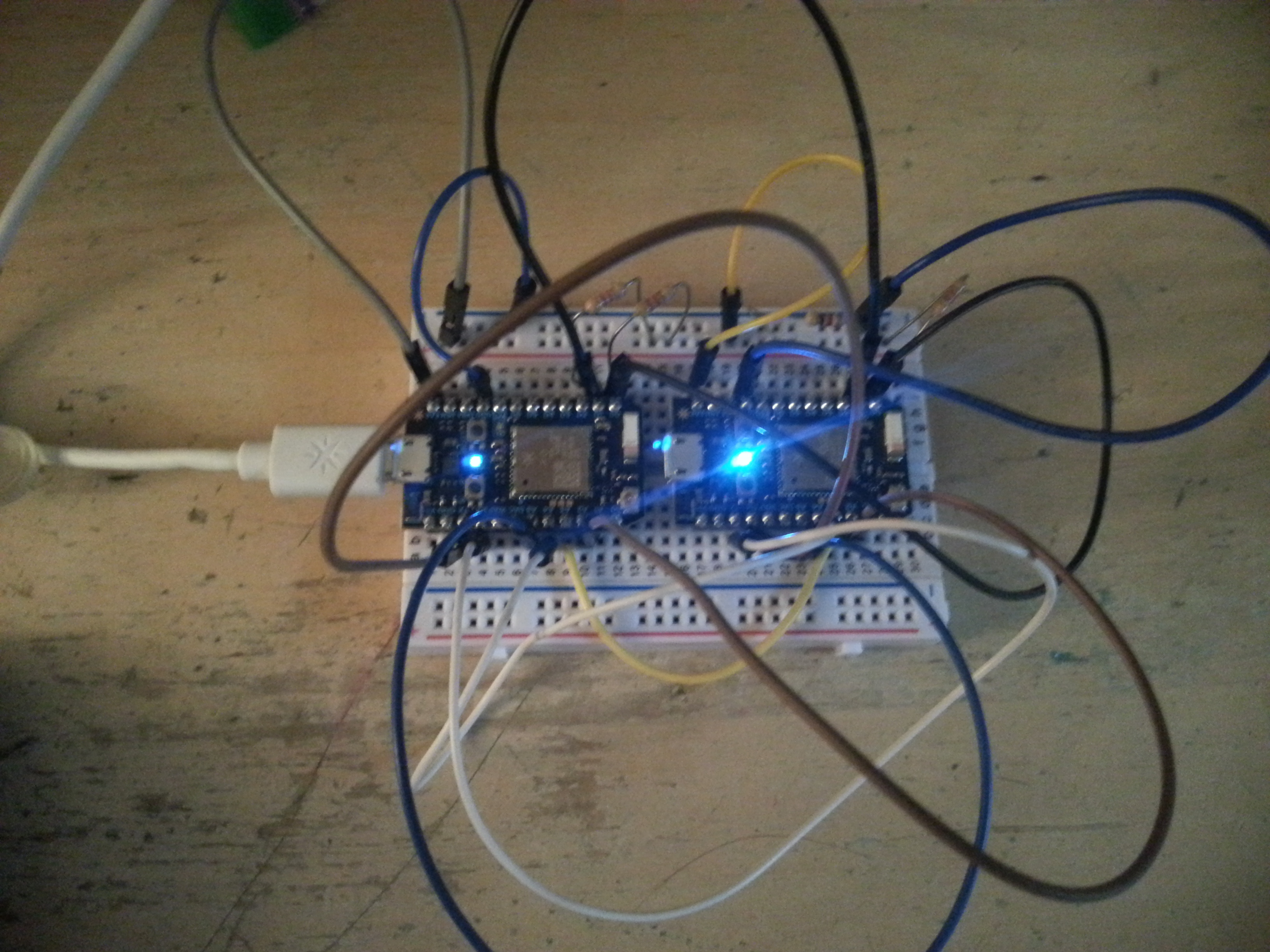
@avtolstoy or @mdma either of you want to add your two cents. I am trying to make some very simple: photon to photon SPI slave and master sketches. Not finding much examples so I have started my own.
I just want to send one byte from the slave to the master and one byte from the master to the slave as simply as possible. For the easiest code do you have to use onSelect and onTranserFinished as the DOCS example shows just below this link?
https://docs.particle.io/reference/firmware/photon/#onselect-
...
Since there is no Master example code I sort of found / changed this sketch
void setup ()
{
Particle.publish("started", "master", 60, PRIVATE);
delay(2000);
SPI.begin(SPI_MODE_MASTER, SS);
digitalWrite(SS, HIGH); // ensure SS stays high for now
// Slow down the master a bit
SPI.setClockDivider(SPI_CLOCK_DIV8);
} // end of setup
void loop ()
{
char c;
// enable Slave Select
digitalWrite(SS, LOW);
// send test string
for (const char * p = "Hello, world!\n" ; c = *p; p++)
SPI.transfer (c);
// disable Slave Select
digitalWrite(SS, HIGH);
Particle.publish("Master Sent", String("Hello World"), 60, PRIVATE);
delay (5000);  // 5 seconds delay
} // end of loop
any suggestions?
...
...
P.S. Presently SPISettings only compiles if I include Arduino.h whereas (Note the extra underscore before SPI)
__SPISettings settings(4*MHZ, MSBFIRST, SPI_MODE0);
compiles fine on its own.
Looks like something to do with
...
Now unsuccessfully trying:
As a master.ino
__SPISettings settings(4*MHZ, MSBFIRST, SPI_MODE0);
void setup ()
{
Particle.publish("started", "master", 60, PRIVATE);
delay(2000);
SPI.begin(SPI_MODE_MASTER, SS);

digitalWrite(SS, HIGH);  // ensure SS stays high for now
}
void loop ()
{
char c;
digitalWrite(SS, LOW);     // enable Slave Select
SPI.beginTransaction(settings);

c = 'A';
SPI.transfer(c);
SPI.endTransaction();
digitalWrite(SS, HIGH);  // disable Slave Select
Particle.publish("Master Sent", String("A"), 60, PRIVATE);
delay (5000);  // 5 seconds delay
}
...
....
And as a slave.ino
byte val;
String myIncoming ;
bool myGotData = false;
__SPISettings settings(4*MHZ, MSBFIRST, SPI_MODE0);
void setup() {
Particle.publish("SPI slave", "Started", 60, PRIVATE);
    delay(5000);
SPI.begin(SPI_MODE_SLAVE, A2);  // slave select on PIN A2
}
void myOnSS(uint8_t state) {
if (state){
myGotData = true;
SPI.beginTransaction(settings);
digitalWrite(A2, LOW);
myIncoming = (char)SPI.transfer(val);
    SPI.endTransaction();
    digitalWrite(A2, HIGH);

} else { myGotData = false; }
}
void loop() {
SPI.onSelect(myOnSS);
delay(1);
if (myGotData){
    Particle.publish("SPI received bytes="+String(SPI.available()), myIncoming, 60, PRIVATE);
    delay(10000);
    myGotData = false;

}
}
Still having no luck. @rickkas7 do I have to manually set all pins to the correct inputs and outputs like some SPI Arduino sketches?
This has some good info


 . No mater how many times I tell the students not to hook a non-micro servo up to the Photon, every few weeks some creative student gives it a try.