I am reading wrong Voltage ADC values from the ADS 7828 board in the particle PHOTONH through I2C channel.
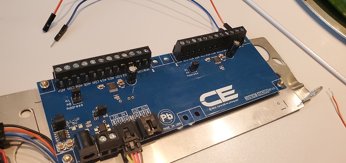
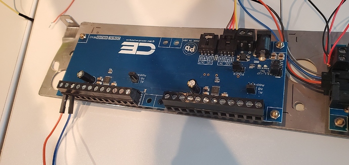
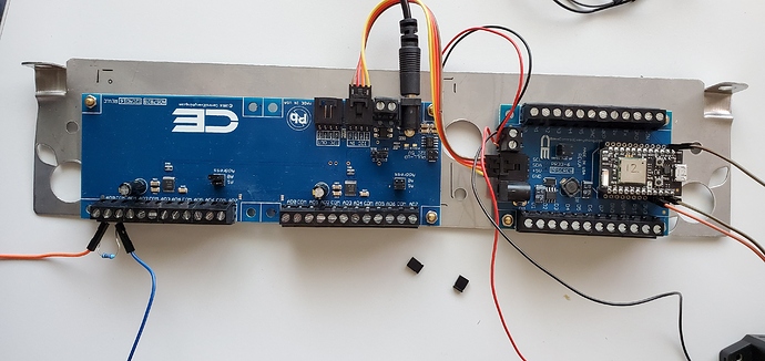
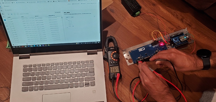
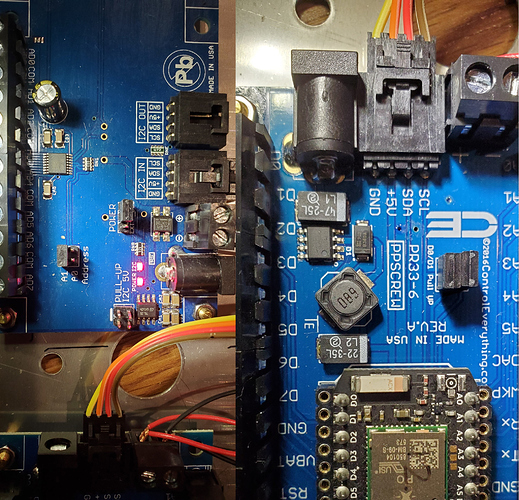
Even I haven't given any input to AD0 & COM0 lines, I am reading random voltage values between 3.1 - 3.9. Actually, it should return zero values because I haven't attached any input. Please refer below pics for more details. Actually, I don't understand why I am reading wrong values through I2C. Please refer below source code and detail explanation of my input. If you guys have any idea on this issue, please provide your suggestions.
NOTE: we found reference of this source from the github community and modified it based our need.
// ADS7828 I2C address:- A0 = 0x49(73) & A1 = 0x4A(74)
#define Addr 0x49

int raw_adc = 0;
double Current = 0;

void setup()
{
  // Set variable
  Particle.variable("Current", Current);

  // Initialize I2C communication as MASTER
  Wire.begin();

  // Initialize serial communication, set baud rate = 9600
  Serial.begin(9600);
  delay(300);
}

void loop()
{
  byte data[2];

  // Start I2C Transmission
  Wire.beginTransmission(Addr);

  // Send command byte
  // Single Ended inputs
  // Channel: 0 (zero) selected
  // Internal Reference ON and A/D Converter ON
  Wire.write(0x9C);

  // Stop I2C transmission
  Wire.endTransmission();

  // Request 2 bytes of data
  Wire.requestFrom(Addr, 2);
   //Particle.publish("Digital: ", "read two bytes");

  // Read 2 bytes of data
  // raw_adc msb, raw_adc lsb
  if(Wire.available() == 2)
  {
    Particle.publish("Digital: ", "after two bytes read");
    data[0] = Wire.read();
    data[1] = Wire.read();

    // Output data to dashboard
    Particle.publish("data D0: ", String(data[0]));
    Particle.publish("data D1: ", String(data[1]));

    // Converting the data to 12 bits
    int raw_adc = ((data[0] & 0x0F) * 256) + data[1];
    double Voltage = raw_adc * 0.0012207;
    Particle.publish("Digital: ", String(Voltage));

    // 1 sec delay
    delay(1000);
  }
  else
    Particle.publish("Digital: ", "Not available");
}
I2C READ (AD0 & COM0) or (ADx & COMx)
Output: 3.2 - 3.8 voltage values
========================================================================
1) CHANNEL SELECTION CONTROL
SD C2 C1 C0 CH0 CH1 CH2 CH3 CH4 CH5 CH6 CH7 COM
-----------------------------------------------
1 0 0 0 +IN - - - - - - - –IN
2) POWER DOWN SELECTION
PD1 PD0 DESCRIPTION
--- --- ---------------
0 1 Internal Reference OFF and A/D Converter ON (When Power input from I2C)
1 1 Internal Reference ON and A/D Converter ON (When power src from external 12V pwr supply)
NOTE: I used both options but I am getting wrong values/
3) DEVICE ID SELECTION
A1 A0
-----
0 1 -> device ID '01'


 , which not gonna work correct ! Could you move delay(1000) from loop (not elegant at all but just for testing purpose) and then place at the end on my function ParticlePublish like here:
 I mean I’m not sure if this even gonna work !( it’s compiling fine)
