I am receiving my first core as a xmas present and got a sneak peak and I am absolutely surprised how small it is!
However I have a few questions mainly around the voltage logic, as I have programming skills but next to nothing in electronics except for some tinkering on an Arduino UNO.
Since the Spark runs on 3.3V does this mean I wont need resistors on
LEDs or is the .3V still too much?
If I have a sensor such as a RF Receiver or temp. monitor which runs
on 5V power, will the data line need to be reduced to 3.3V? I assume
in such scenario I can power the 5V through the VIN (using USB)
When I do flash my own code onto the Core how do I get the Tinker
code back?
Do I need to do any prep work before I use the Core, such as
upgrading the C3300 firmware?
Sorry for all the questions and I am sure there are more to come but I cant wait to be part of the community
The thing with LEDs is not actually the voltage but the current. Once your voltage exceeds the typical forward voltage, the diode opens and the current shoots up and you need to limit this current with a resistor. The only difference between 5V and 3.3V is that you’ll need a smaller resistor to limit the current to e.g. 20mA. As you assumed a forward voltage of 3V for you LED you’d need 15 Ohm (0.3V / 0.02A), while vor 5V you’d need (5V-3V)/0.02A = 100 Ohm. But I’d rather go for 2.5V forward drop and take a 33 or 47 Ohm resistor.
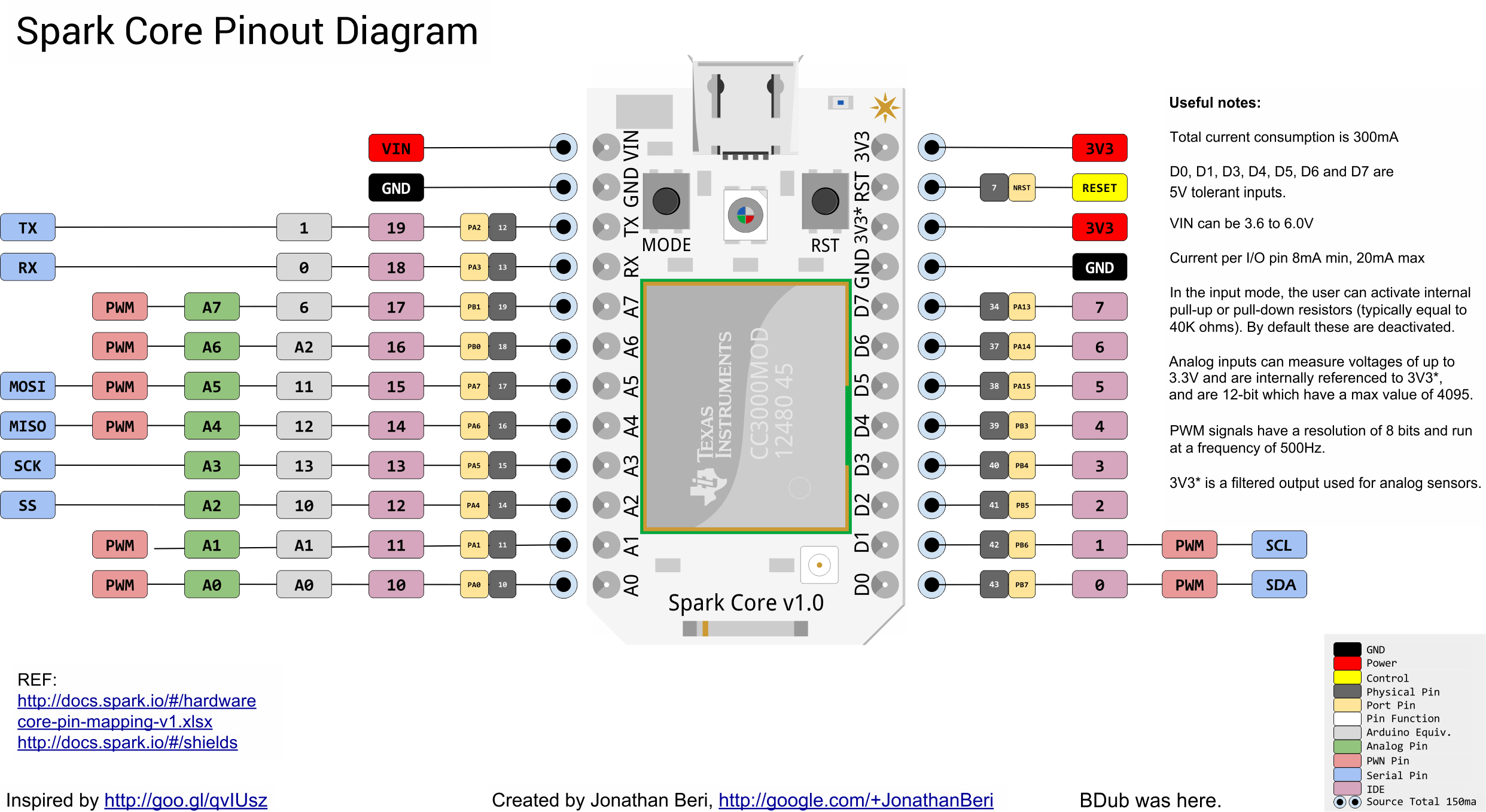
The best would be to use a level shifter (chip or home made with transistors or use the Spark Shield Shield), but you could get away with using some of the 5V tolerant Core pins (only 7 of 18 see docs) and hope that 3.3V is considered HIGH by the sensor.
To get Tinker back, you could use the inbuilt function of the Tinker Apps (iOS & Android), or do a factory reset, or just flash the source via the Web IDE, …
Since I understood that you’ve just recently ordered your Core it should already have the latest CC3000 firmware on it, so out the box and GO! GO! GO!
As far as the sensor voltage goes: depending on how much current you require (<200mA), you can power it from the V_in. As far as I know, most input pins are 5V tolerable, but be sure to check the docs for that (hardware section - I/O)
You can get Tinker back by performing a factory reset, clicking the “install Tinker” from the app, of flash the code from the IDE (look for it in the docs under ‘Tinker’ I believe)
With the current Cores, the patches are already applied, so just unpack it and play
Thanks for the input guys, I am really eager to get my hands dirty but I must wait until the 25th and even then wait until the celebrations are over
I did order the Shield Shield as I thought that would be a safe route for my tinkering, however due to its size it would be nice to try to avoid using it
Really do need to get up to speed on all the electronic terminology and calculations , however I am glad to hear that some of the pins are 5V tolerable so hopefully should be ok
Another question I have is can I use the analog pins for digital use? eg. DigitalRead(A0); I assume I could always do a programming method and use the AnalogWrite(A0, 0) or AnalogWrite(A0, 1023) to do LOW and HIGH, then using a 50% calculation on the Read operation to determine if its LOW or HIGH?
PS. I think it might be useful if its not already around, a “Arduino 101 Migration FAQ” to help answer these probably common questions, as I assume most would be coming from the Arduino starter kits
There are numerous options for logic level shifting, depending on exactly what you want. If you’re like me and can’t be bothered making something from discrete components, you could try something like these bi-directional shifters: http://www.adafruit.com/product/395. If you don’t need them bi-directional, there are cheaper options like the CD40109B (the datasheet’s not the best, but I’m using them quite happily).
The max value you can analogWrite is 255, but as @Nye said, you can digitalWrite() and digitalRead() on A-pins just the same - in fact the implementation of analogWrite() does actually do a digitalWrite() internally when you send 0 or 255.
As a little perk, you can even digitalWrite()/digitalRead() the RX and TX pins, too. So you do actually have 18 IO pins to your disposition
On the other hand if you do analogRead() your maximum reading on the Core will be 4095 since it's a 12bit ADC compared to a 10bit ADC (max 1023) on a standard Arduino.

 Spark Community!!!
