I have had success switching with mosfets recently, mostly thanks to a previous post
But now I tried to wire 7 of them in parallel and none of them work. I took one out and wired it exactly as is on a separate board, still nothing. The link above contains the circuit I believe I have wired in the following pictures. I am almost certain its something small and that I am going to feel dumb when Its resolved. Thanks in advance.
I think we may both be working on similar projects. In that I am using the Photon to turn on water for my plant irrigation system using a MOSFET. This is a great use for the Photon and I wish you luck in your efforts.
I am implementing the same circuit in my approach so perhaps I can help.
Here is the circuit that you need to implement:
In looking at the schematic in your previous post, I think you are missing one important component - RGS. This resistor holds the gate low until your Photon sends the HIGH signal to open the gate.
Also, in your previous post, it looks like you are using a linear regulator to step down the 12V supply to 5V. I am sure you wired it correctly, but the schematic does not align to the way the pins are laid our physically which should look like this:
I looked at your pictures in this post and and a bit concerned to see red wires on both of the top rails on the breadboard. Perhaps you could add RGS and then use red jumper wires for power and black for ground which would make it easier for me to see what you are doing.
What does that mean? Are they always off, always on, randomly switching? Which MOSFETs are you using; are they the same as the ones you were using in your linked post?
@chipmc, while it's probably a good idea to use a resistor tying the gate to ground, it shouldn't be the cause of the OP's problem as long as the pin on the Photon is in OUTPUT mode - if the pin is LOW, the gate will already be connected to ground without that RGS resistor. Having that resistor would keep the MOSFET off in the case where the pin somehow got into a high impedance mode (i.e. INPUT), or the Photon failed or was off, while the MOSFET was still connected to power.
Grounding the data pin has worked! I do not have a voltage regulator in my circuit currently, do you think I would need one?
For the heck of it once the valve was switching on and off i unplugged the jumper wire running connecting to gate to ground and it continued to work. This makes me think that there is more to this that I do not yet understand. In
@Ric I am using a RFP30N06LE on the part of circuit I decided to build on a separate bread board, the one pictured above. I havent tried it on the big circuit yet as I am working with limited time. I will later to night and reply to your post.
The issue I was seeing which caused me to add the RGS resistor from the gate to ground and that enabled the circuit to work for me. I suspect that when the Particle device (I use the Electron for my irrigation system) is rebooting, the IO line is in an undefined state which, for me, resulted in the solenoid opening and my project watering when it should not. Adding a connection to ground (I used 100k) kept the gate from “floating” and ensured the solenoid would stay closed until my program directed it to open.
I would not recommend wiring a 7805 linear power supply in each of the 7 circuits as you will disparate a lot of energy as heat. It seems from your picture, that you have a DC power supply which should be able to provide the power needed for all seven of your pumps / solenoids. However, you should look at the following:
1)Assuming they all work at the same voltage, what is the maximum possible current? (all “on”?)
2) Can your power supply provide that current?
3) Can your MOSFETs handle that current?
4) Can your wiring or traces (if using a PCB) handle that current?
If you have concerns about any of the above, you should consider an over-current protection element such as a fuse or a resettable (PTC) fuse.
Thanks for the indepth response Chip, much appreciated. So all of the solenoid values are running relatively low amperage (somehwere in the range of 800 mA) at 12v. There will be around 4 of those solenoid vales. Then at least two pumps one high power (12v 6A max) and one lower (12v 2A max). I plan on wiring these on an entirely separate breadboard because something about the high amperage sketches me out no pun intended.
The DC power supply i have is 150W at 12 V. I have left ample room for it to power all of my electronics at worst case scenario.
Should I run a 12V linear voltage regulator to regulate the rails that power all of my 12V valves rather than running a separate regulator to each circuit.
Thanks for the details, it helps to know some of the specifics. As @ScruffR has pointed out, I think we are still not all understanding what you want to do. For example, a 12V regulator is typically used to deliver a 12V output from a higher (buck) or lower (boost) voltage. If you already have 12V, then you don’t need a regulator at all but may need:
Bypass capacitors to help prevent temporary voltage dips when a motor is switched on
Diodes (like you have in your circuit) to dump reverse current when motors are switched off.
Some current protection devices like fuses or resettable PTC fuses
Also, as @ScruffR pointed out, solder less breadboards are not intended to handle this amount of current. From what I can see on-line solder less breadboards are typically only used for 1-2A current circuits.
Have you considered buying a commercial relay board rated to handle your needs? Otherwise, you will need to use a soldered breadboard such as the Adafruit perma-proto and use solid core wire to to handle connections requiring more than 2 Amps.
I guess I should have been more clear, my apologies. For the project I am doing I plan on having this one power supply power the entire system. I’m trying to make a stand alone garden that plugs into the wall. So he supply would have to power all of my pumps, valves, and sensors as wells as my Photon. I know ill need a 5v linear regulator and now i know i wont need a 12V.
In regard to the board; I have had a feeling that i would eventually need to make the switch. I so far have been just testing everything individually before i start to put it all together. Do you think I should do my entire circuit on the soldered board or just the higher power things?
Now back to the original problem, for the heck of it I tried the above circuit as is and it worked from the jump without the jumper connected to the resistor. When i connected the photon while it was running the valve failed to open and close. So essentially the problem i was having that made me want to come here for support was fixed by the solution you suggested and now that same solution doesn’t work and the original problem works. Any thoughts on why this is acting so strange?
It seems that we have made some progress here. But, just to recap and to make sure I have this right.
For your project, all your solenoids and pumps require 12V which you will supply with a single 150W 12V power supply.
In addition, you need to power your Photon and that will require a 5V buck regulator (linear or switched, your choice) to reduce the 12V down to 5V.
We agreed that any of the components that draw more than 2A would need to move to a soldered breadboard and those circuits would need solid core wire to carry the higher-current.
I would suggest you move your entire project to the soldered board if you intend to leave it in operation for any significant amount of time. I would also suggest you use consistent colored wires and try to be neat to make troubleshooting and future improvements easier.
As for the weird behavior, I think you need to troubleshoot this in a methodical manner. The first step is to isolate the systems and validate them individually such as the MOSFET circuit and the Photon control lines. Ideally, you can confirm that each is working correctly before you connect them. Then, if you are getting an unexpected result, you may need to make some measurements of what is happening in your circuit. For example, if you could measure the Photon pin that is controlling the MOSFET, you could validate it is delivering the right signals. An oscilloscope is ideal for this as some issues are transient in nature and may not show up on a volt meter.
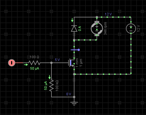
Sometimes a circuit simulation is helpful. Here is one I created for this circuit (you will need to use Chrome to open this link)
Can you try to collect some more data and let us know what you find?
Chip, Thanks again for such great information. I’lll have to work to further isolate the problem and get back to you as time allows. I have tried previously to wire 4 of these circuits to a soldered board but none of those work, from what i assume is the same problem, and that is what drove me to move back to the bread boards. Ill have to somehow find the problem using some of the tools you’ve provided and then move to the soldered board.
The regulator I am using is linear, L7805CV, I have yet to try and wire it up but it looks simple enough, one in, one out, and a grounding pin. Any tricks of the trade when working with those? Now that i think about it, I have the power shield which has an input for 7 to 20v that it can use to power the board and charge the battery. If i were to go that route should I use a 12V regulator or a 5V, or just wire straight to the power supply (this seems wrong). The only thing that concerns me is the power shield somehow getting overloaded with current and damaging the board.
I am not going to mark this as solved until I figure this out, and report back for others having similar issues.
Before I start wring it up I wanted to post a picture of my diagram. This is the one i plan to build for all of my switching circuits. I want to know if i’m using the decoupling capacitor in the correct way, and i also added the resistor to ground the data pin as @ScruffR suggested. If i were to add a fuse where in the circuit would make the most sense? I would think in-between the load and the MOSFET, is this correct?
Your 220 ohm resistor to ground is probably too small. If R1 is also 220 ohms, the voltage at the MOSFET gate will only be 1.65 volts (half of 3.3 v) when D0 is HIGH. The threshold voltage for your MOSFET is 1 to 2 volts, so it might work for some devices, and not for others. A 10k ohm resistor should be more than adequate to make sure the gate stays low if D0 is in a high impedance state.
To illustrate the meaning of your flyback diode D1 I’d actually move the coil of your solenoid into the main route.
This should also help to see that the polarity of D1 is wrong. Flyback diodes are meant to be blocking in normal mode and only short back the negative EMF that’s produced when the magnetic field collapses.
Also the polarity of your battery is inverted - you got the + pole on GND.
I have made the changes to the circuit per your suggestions. do you think 100nF is enough capacitance for my application? I am slightly confused by your change regarding the flyback diode but after some googling i believe I have it right. Does this look correct?
I have wired up the above circuit and the simple code that I am running to test it. And am still having the problems that led me to open this topic.
When I plug in the power supply I the valve, normally closed, opens but no switching. I have tried the above circuit with and without the 10Kohm, to no avail. When the power supply is unplugged the valve slowly closes. When I measure the drop across the diode it reads ~12v. I feel their is something I am missing. here is the code I am running;
I don’t understand what your problem is. In a post you made 7 days ago, you said, "Grounding the data pin has worked!"So what’s changed since then? Didn’t you have it working at that point?
Sorry for the lack of clarity, as I am just frustrated with this circuit.
Grounding the data pin did work initially, but sparingly. Sometimes I would have to unplug the valve then replug it, then it would switch as intended. Other times it wouldn’t switch at all just be open until I unplugged it. I know that it’s something simple and when I get it ill kick myself for stressing this much about it, but in the moment it sucks.
I feel that every change that is suggested works for a few cycles of turning on and off the power supply and/or the photon, but nothing has working consistently? Is their a set of guidelines i should follow?
Thanks for your help, I don’t know what’d i’d do without this forum.
EDIT: here is a picture of the trouble maker, I spread the components out to try and make sure it was all correct, the power supply plugs into the rails that are second closest to the camera.