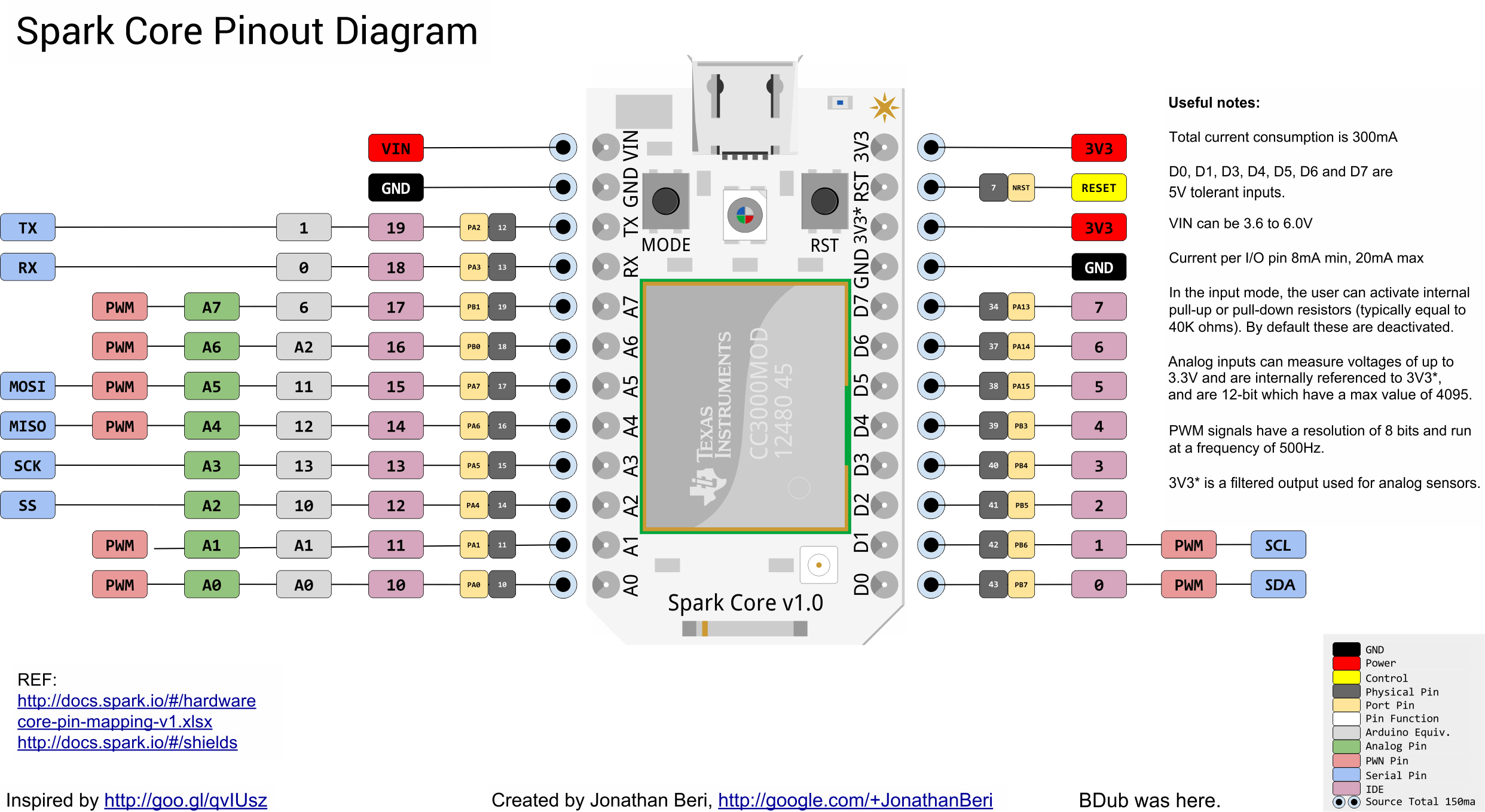
I am trying to read a pH level from an Atlas Scientific pH circuit using I2C. I am able to read values with an Arduino Uno with no problems, but I get garbage data when reading with a Spark Core. Some googling suggested that I need to add pullup resistors to the SDA and SCL lines. Looking through the documentation I noticed that I can activate internal pullup resistors. I tried various API calls to activate the internal pullup resistor, but never got it working. Finally I added external 10k ohm resistors to the SDA and SCL lines and my program stated working as expected (see hardware setup below). While I am happy that my circuit works as expected, I am still perplexed as to why the internal pullup resistors did not work. Has anyone got the internal pullup resistors working with I2C communication?
@csjall, the internal pull-up resistors cannot be activated when using I2C by design. The bus requires devices to use open-drain/open collector outputs so as to go “open” when no active, allow multiple devices to share the same I2C lines. As such, external pull-up resistors are required, as you discovered. This applies to Arduino as well.
@peekay123 - are the external pull-up resistors are required even if the voltage levels of I2C device is 3.3V or are they necessary only when the external I2C device is using 5V?
Here is a useful, if verbose, reference. The old standard 5V/400KHz bus pullup values of around 2.2K should be good, but as the supply voltage of newer designs drop (e.g. to 3.3V or lower), it is worth recalculating the value to make sure you still have a solid design.
I like 4.7k ohm for 3.3V systems. There is essentially no current entering the inputs in CMOS devices (the STM32F103 specs 1uA max), so you are really just overcoming input capacitance (generally spec’ed as 5pF per pin) and wire capacitance (depends on your circuit).
As a rule - as the speed of the bus goes up and/or the voltage swing goes down, the value of the pull-up resistors goes down.
Frankly, for most hobby stuff, 2.2K-4.7K will work for anything but the most pathological fast bus (400KHz), and 4.7K-10K will work for slow (100KHz) busses.
One other quick point: in the datasheet for the STM32F103 used in the Core, they show on page 70 an i2c circuit with 4.7k ohm pullups and 100 ohm series resistors at the processor pins. These series resistors limit the slew rate, particularly with long wires, but generally are not needed.
One little foot note only only one set of resistors , so if you have devices with inbuilt resistors , you my need to remove the resistors from others, which is normally by cutting tracks.
According to the I2C spec from NXP/Phillips (the designers of I2C) the optimum bus loading is 3 milliamps, or about 1.2K for a 3.3V system. Most of the I2C PCBs available have pull-ups in the range of 4.7K to 10K ohms. You can have up to 4 devices with 4.7K pull-ups connected, or 8 for 10K, and everything should be OK. Just make sure all the paralleled resistors of multiple boards don’t exceed 3 milliamps total load.


