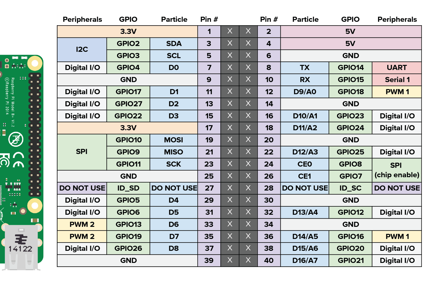
I made it through the LED/Web LED examples OK using this Datasheet to figure out which Pi pins correspond to Particle device pins and edit the example code accordingly.
However now I’ve gotten to the next example, the photoresistor. I’m having trouble here since the Pi doesn’t have any analog pins, and the example code is written for a Particle device that does. I do have an MCP3008 Analog-to-Digital converter chip hooked up to my Pi, but I don’t understand how to reference the CH0 through CH7 pins that it provides.
If you could help me with how to do analog input on Particle through the Pi, especially in the context of the Photoresistor example in the Getting Started guide, it would be much appreciated!
@nrobinson2000 I do appreciate your quick response and wiring suggestions. I’m a bit of a coding newbie but I’ve toyed with Arduino before… through the Arduino IDE. I’m new to Particle and was waiting for the Raspberry Pi beta to try it out since I don’t own any Particle hardware.
Presuming I can figure out how to include that library in my project in the Particle IDE, how would I reference the pins in this section of the example code?
// We're going to start by declaring which pins everything is plugged into.

int led = D0; // This is where your LED is plugged in. The other side goes to a resistor connected to GND.

int photoresistor = A0; // This is where your photoresistor is plugged in. The other side goes to the "power" pin (below).

int power = A5; // This is the other end of your photoresistor. The other side is plugged into the "photoresistor" pin (above).
// The reason we have plugged one side into an analog pin instead of to "power" is because we want a very steady voltage to be sent to the photoresistor.
// That way, when we read the value from the other side of the photoresistor, we can accurately calculate a voltage drop.
Lets say my photoresistor is plugged into CH0 (since A0 isn’t a thing in my setup). How would I reference it here? What if I had second analog device plugged into CH1?.
Hi again. First off, thank you for the example code. It does indeed compile and I am able to use the example HTML to flip my LED on and off.
Where I’m stuck now (and this may be user error, I’m still investigating), is that result that I’m getting from the variable analogvalue seems to be jumping between 0 and 2047 depending on whether I have my LED toggled on or off.) That seemed fishy to me since it is an analog sensor, I expected more variation. And indeed, if I leave the LED out of the equation and just flip off the light switch in the room where I’m working on this, see no change in the variable value.
That tells me I’m really reading back some sort of on/off state rather than the light level picked up by the photoresistor. I’m going to double-check my wiring and report back… but if you have any ideas here feel free
Actually editing out my previous post (lol) because I’m realizing I didn’t properly wire up the ADC. Let me at least do that and then see how things look.
Not worth investigating beyond that until I get things properly wired. I think I was just reading the powered/non powered state of the whole setup.
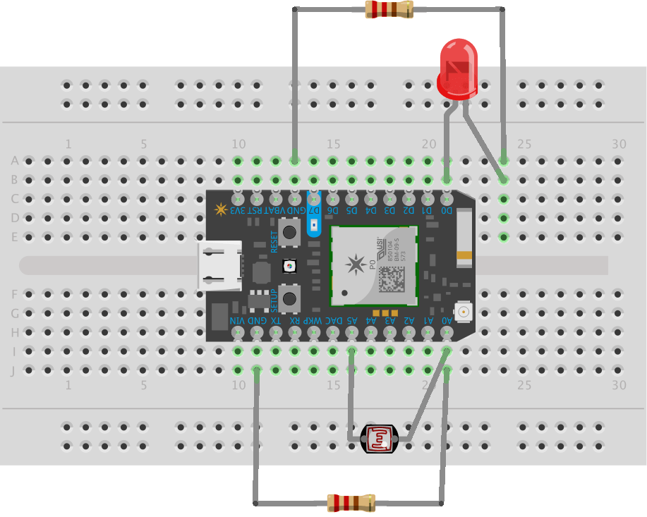
I’ve now (ostensibly, I can take pictures) wired up the MCP3008 OK, but I’m still seeing similar behavior. Can I ask about the wiring for the other half of the resistor?
Keep in mind I’m using this (Non-pi) image from the Pi tutorial:
In my case I have one leg of the Photoresistor on CH0 of the MCP3008. A 10K resistor connects it to Ground as well. The other leg is on CH5. I know we still have A5 in the code and am wondering if this could be part of the trouble? The comments in the example code seem to imply that it uses that pin for a consistent power source, so I tried hooking it to 3v3 as well, but I get the same result, analogvalue toggles between 0 and 2047 depending on the state of the LED.
I will see if I can take a picture that actually shows this amidst the jumble of wires.
Ah I think I might see my mistake (though I have to try it). When you say A5, it needs to be connected to GPIO16 right per the above diagram, right? I had it hooked to CH5 of the MCP3008 which we’re not referencing.
Does it matter that GPIO16 on a Pi is not an Analog Pin?
I’m also seeing that the resistor in the example image appears to be 330 Ohm instead of 10K. I’m not sure if that matters here but I’ll swap that out…
A5 is what powers the photoresistor. It is just doing digitalWrite( HIGH) to give consistent power. It is GPIO16, but you can change it in the code if you want.
Whats weird is that the LED doesn’t even need to be part of this equation right? Presuming I have a light switch in my room? I would just be interested in reading a changing analog value here, no matter the light source.
The part I can’t figure out is why that result is changing at all when I toggle the switch via the provided HTML, since I don’t think its changing based on actual light received by the photoresistor.
Gotcha, I appreciate the help. It very well might be something I’ve missed as well, and I’m a bit burnt out for the day. Perhaps I’ll bite the bullet and buy some Particle hardware to start with since that seems to be what the documentation is currently aimed at. I understand the Pi stuff is still in beta.
I’m not sure if you work for Particle or are just a friendly community member, but my feedback if they are watching is that they should update their Getting Started guide for Pi to reflect examples that are doable on the Pi (though you’d need an ADC at some point to do most interesting things).
At least if they had one there would be less doubt about things like the appropriate library. Something tells me I’d have this working on a Photon in about 10 minutes
I'm just a "friendly community member" trying to help other members. Particle is working on improving their documentation as the Raspberry Pi beta progresses. I'll make sure that the examples are updated for Raspberry Pi.
Hi - I have loaded nrobinson2000’s MCP3008 files on Particle, and have wired an MCP3008 ADC up as per the pin descriptions in the code to my Raspberry Pi 3. I have a potentiometer wiper going to Channel 0 (Pin 1) on the ADC, and a second pot’s wiper going to Channel 1 (Pin 2) on the ADC. I want to flash the LED ON for a period determined from pot 1’s setting, and OFF for a period determined from pot 2’ s setting.
In a separate off-line set-up, my circuit works with the gpiozero MCP3008 class, but I’m struggling with the Particle code to get the system going under Particle. How do I get the ADC Channel 0 and Channel 1 values? analogvalue0 = adc.readADC(0); gives a value of zero, and analogvalue1 = adc.readADC(1); gives the value of 2047.
Neither of these values are affected by adjustment of the potentiometers. Can you please help?
Kieran Cranley