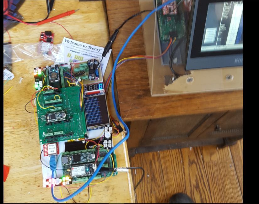
SPI1 slave Electron to Teensy 3.6 SPI1 master.and Teensy3.2 I2c master for Photon and DIGOLE and a couple of NANOS also hard enet TCP to MEGA2560 Modbus and KINCO TCP client. Next ModbusDMA SPI for the 3.6 and electron…id show the cell phone but i had to take the picture. Im getting close…yippy.
4 Likes
Well its a start…I got my wiznet 820 chips now to put that in place of the 5100 hanrun…I was thinking of using a DTR flag from the Electron as sort of a token request for message transfer. That way the master could send a generic request and the slave could “advise” the master what to ask for…sort of like a token passing scheme. Head tilt optional…maybe not needed?

The project looks interesting but I’ll admit I’m not exactly sure what you are doing. I see a lot of cool components there. Can you explain what’s going on in a bit more detail?
Sure my pleasure…this started because I have a great deal of legacy devices who are on hard TCP. For security reasons and reliability these must remain on hard Ethernet. I have an issue (maybe a disability) in using the SPI port on a photon/Electron with the Ethernet library on a second (desirable Ethernet port because of class conflict in available libraries that use the TCP facility. SO…I got a hard Ethernet port and a whole lot of computing power over in the Teensy. I will keep my mission critical tasks over in the Teensy and just mirror a data table for use by the particle in achieving connectivity via cell phone or wifi. The device gives me autonomy over whether I am actually connected or needing to do anything with the outside world. The use of SPI gives me bidirectional messaging at a high rate of speed. Truth be told I could for right now achieve this with a serial port for the pair. But with the master using the DTR in a context sensitive manner this could be used as a “multi drop” arrangement. What will come later is a small micro LAN of processors using SPI as a bus. With this architecture I get super bus speed. And a demand driven communication request/ response protocol. one thing I would add is a DTR to the SPI slave…right now there may be significant latency in the response from the particle…so I want to have my transaction driven by an interrupt not just chip select…I have a bunch of stuff going on so I only get to this briefly.
The other thing I ge from this is a local boot loader for the Teensy…and FTP for files to get there and get updates to my teensy…I wish I new more but this looks like it will bring together the HM in a nice little coherent platform for remote deployment to a network too.
2 Likes
I guess I will have to get a little bigger touchscreen

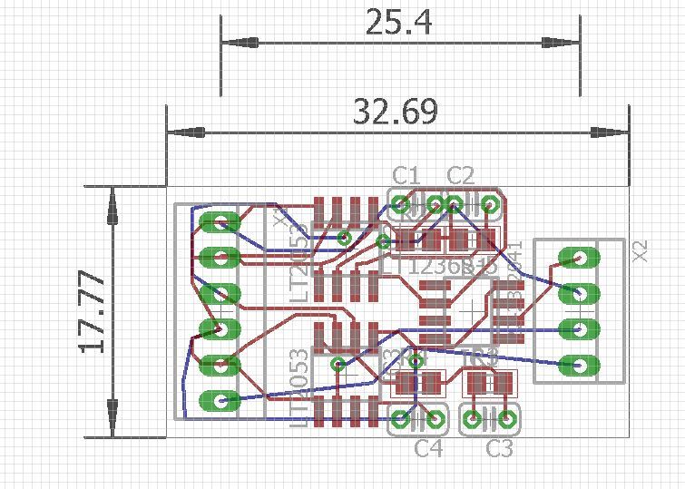
with the PI Zero as the HMI…I will put LTC2053 pre-amps on the 10 differential inputs. as an option…
dual 2053 preamp (with reference) BOB that plugs into above. slice the analog traces to the stereo phono jacks to use the preamps
.
Well I am pretty sure I have it ok electrically except using the A2 pin on the electron for SPI1 SS in slave mode…I know in Master this is set as output I use it as the select pin with
…the teensy seems fine…not much out there but…I manage to crash the electron with the slave like this…the electron controls the DTR pin so the teensy wont run it over…the master waits for the slave to be readyany slave can pull the DTR low for a while…for now the Electron is the only slave on the line. I have the Teensy lights showing the DTR (B5) electron and the RTS (SS) A2 lines of the electron assoon as the ELECTRON lets the DTR line go high…the TEENSY pulls the ELECTRON low at A2 chip select and runs a 2MB SPI transfer of 64 bytes…anTeensy just plows along waiting for the electron to reboot. for another killing cycle…dunno.
// This #include statement was automatically added by the Particle IDE.
#include "neopixel/neopixel.h"


#include "application.h"

// #include "neopixel.h" // use for local build

SYSTEM_MODE(AUTOMATIC);

// IMPORTANT: Set pixel COUNT, PIN and TYPE
#define PIXEL_PIN 2
#define PIXEL_COUNT 8
#define PIXEL_TYPE WS2812B

typedef struct{
  char Pred;
  char Pgreen;
  char Pblue;
}
PCOLORS_DEF;

PCOLORS_DEF pcolor[10] ={
  0,0,0, //black
  36,12,5, //brown
  48,0,0, //red
  48,16,0,  //orange
  48,32,0, //yellow
  0,48,0, // green
  0,0,48, // blue
  32,0,32, //violet
  32,32,32, //grey
  84,84,85 //white

};

Adafruit_NeoPixel pixels = Adafruit_NeoPixel(PIXEL_COUNT, PIXEL_PIN, PIXEL_TYPE);

// Prototypes for local build, ok to leave in for Build IDE

unsigned long int AIRtime = 100000;
static char rx_buffer[64];
static char tx_buffer[64];
static uint32_t select_state = 0x00;
static uint32_t transfer_state = 0x00;
const int DTRPin = B5;
char Mb_R[64];


void onTransferFinished() {
    transfer_state = 1;
}

void onSelect(uint8_t state) {
    if (state)
        select_state = state;
}


void setup()
{
  pinMode(DTRPin, OUTPUT);
  digitalWrite(DTRPin, LOW);
  pixels.begin();
  pixels.show();
  delay(3000);
  Mb_R[CIP_SI] = 0x1; // CIP Step color.
  Mb_R[DRAIN_SI] = 0x2; // Drain Step color.
  Mb_R[WASH_SI] = 0x3; // Wash Step color.
  Mb_R[RINSE_SI] = 0x4; // Rinse Step color.
  Mb_R[FRINSE_SI] = 0x5; // Final Rinse Step color.
  Mb_R[SAMPLE_SI] = 0x6; // Sample Step color.
  Mb_R[PURGE_SI] = 0x0; //initialize purg of lines.
  Mb_R[ADC_VAL] = 0x7;// Initialize all pixels to 'off'
  UpdateLights();
  for (int i = 0; i < sizeof(tx_buffer); i++)
      tx_buffer[i] = Mb_R[i];
  delay(1000);
  SPI1.begin(SPI_MODE_SLAVE, A2);//this was D5 but A2 is closer
  SPI1.onSelect(onSelect);
  SPI1.setBitOrder(MSBFIRST);
  SPI1.setClockSpeed(2000000);
  SPI1.setDataMode(SPI_MODE0);
}
void loop()
{

if (select_state == 0);
{
    SPI1.transfer(tx_buffer, rx_buffer, sizeof(rx_buffer), onTransferFinished);
    digitalWrite(DTRPin, LOW);
    while(SPI1.available()<64);
     for (int i = 0; i < sizeof(rx_buffer); i++)
      Mb_R[i] = rx_buffer[i] % 10;
    select_state = 1;
    transfer_state = 0;
}
UpdateLights();
}

void UpdateLights(){

  pixels.setPixelColor(0, pixels.Color(pcolor[Mb_R[STATE_SI]].Pred,pcolor[Mb_R[STATE_SI]].Pgreen,pcolor[Mb_R[STATE_SI]].Pblue)); // Main task state color.
  pixels.setPixelColor(1, pixels.Color(pcolor[Mb_R[CIP_SI]].Pred,pcolor[Mb_R[CIP_SI]].Pgreen,pcolor[Mb_R[CIP_SI]].Pblue)); // CIP Step color.
  pixels.setPixelColor(2, pixels.Color(pcolor[Mb_R[DRAIN_SI]].Pred,pcolor[Mb_R[DRAIN_SI]].Pgreen,pcolor[Mb_R[DRAIN_SI]].Pblue)); // Drain Step color.
  pixels.setPixelColor(3, pixels.Color(pcolor[Mb_R[WASH_SI]].Pred,pcolor[Mb_R[WASH_SI]].Pgreen,pcolor[Mb_R[WASH_SI]].Pblue)); // Wash Step color.
  pixels.setPixelColor(4, pixels.Color(pcolor[Mb_R[RINSE_SI]].Pred,pcolor[Mb_R[RINSE_SI]].Pgreen,pcolor[Mb_R[RINSE_SI]].Pblue)); // Rinse Step color.
  pixels.setPixelColor(5, pixels.Color(pcolor[Mb_R[FRINSE_SI]].Pred,pcolor[Mb_R[FRINSE_SI]].Pgreen,pcolor[Mb_R[FRINSE_SI]].Pblue)); // Final Rinse Step color.
  pixels.setPixelColor(6, pixels.Color(pcolor[Mb_R[SAMPLE_SI]].Pred,pcolor[Mb_R[SAMPLE_SI]].Pgreen,pcolor[Mb_R[SAMPLE_SI]].Pblue)); // Sample Step color.
  if (AIRtime>millis()){
    pixels.setPixelColor(7, pixels.Color(pcolor[P_RED].Pred,pcolor[P_RED].Pgreen,pcolor[P_RED].Pblue));
  }
  else
  {
    pixels.setPixelColor(7, pixels.Color(pcolor[P_GREEN].Pred,pcolor[P_GREEN].Pgreen,pcolor[P_GREEN].Pblue));// Moderately bright green color.
  }
  pixels.show(); // This sends the updated pixel color to the hardware.
  // Magical sprintf creates a string for us to send to the s7s.
  //  The %4d option creates a 4-digit integer.
  digitalWrite(DTRPin, HIGH);

}
Thanks for a place to keep notes…

