Boron - One Year Battery Life Project

All,

I know there has been a lot of interest in long life batteries such as the many posts by @Vitesze. I would like to build on this and explore the possibility of building a Boron based sensor which checks in 16 times a day and whose battery will last a year.

I want to call out the following at the outset:

  • I don’t know if someone has already solved this problem - though I did search the forums
  • I don’t know if I am approaching this problem from the right direction - for example perhaps I should look at a Xenon with a LoRA radio instead of a Boron
  • If I am OK with my starting point, I am not sure I have laid out the right approach.

For these reasons, I am posting this work early and will update it as I go. Please feel free to engage and hep me with this work.

Rationale: I have been building and deploying sensors in parks for some time and, as the number of deployed units grows, so too does the chance that one will fall victim to vandalism. Being able to offer a non-solar option to my customers may make sense where the risk of vandalism is high. A battery powered device would offer more options for hiding and could open up deployment choices that are better (e.g. PIR sensors like shaded spots) for data quality.

I am assuming there are three major elements to this work:

  1. Writing software that reduces the energy budget of a Boron based sensor
  2. Building hardware that enables lower power consumption ( sleep/wake and EN triggers).
  3. Building a power source that could support the energy budget dictated by #1 and #2

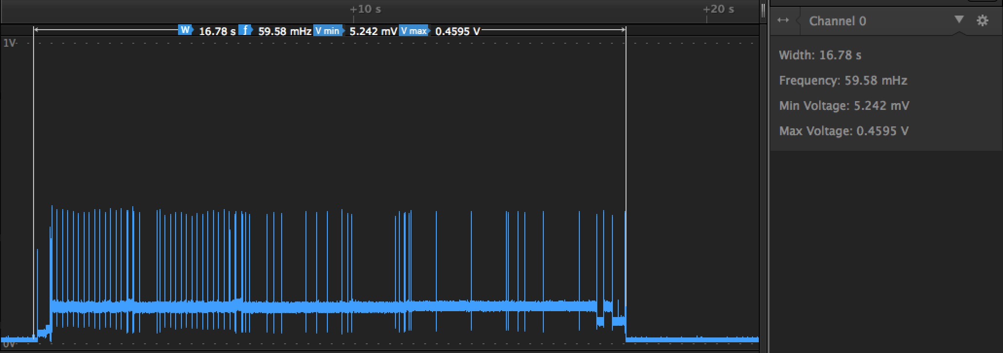
To start with, I built a simple coulomb counter to exactly measure the battery requirements of a real world device. The device I selected was a Coulomb counter based on the Linear Technologies LTC4150 from Sparkfun. I took the sketch from Sparkfun and “Particle-ized” it.

/*
 * Project Coulomb-Counter
 * Description: Count the coulombs used in the Particle device so I can size batteries
 * Author: Chip McClelland adapted Mike's code (see attribution below)
 * Date: 9-22-19
 */

/* LTC4150 Coulomb Counter interrupt example code
Mike Grusin, SparkFun Electronics

This sketch shows how to use the LTC4150 Coulomb Counter breakout
board along with interrupts to implement a battery "gas gauge."

Product page: https://www.sparkfun.com/products/12052
Software repository: https://github.com/sparkfun/LTC4150_Coulomb_Counter_BOB

HOW IT WORKS:

Battery capacity is measured in amp-hours (Ah). For example, a one
amp-hour battery can provide 1 amp of current for one hour, or 2 amps
for half an hour, or half an amp for two hours, etc.

The LTC4150 monitors current passing into or out of a battery.
It has an output called INT (interrupt) that will pulse low every
time 0.0001707 amp-hours passes through the part. Or to put it
another way, the INT signal will pulse 5859 times for one amp-hour.

If you hook up a full 1Ah (1000mAh) battery to the LTC4150, you
can expect to get 5859 pulses before it's depleted. If you keep track
of these pulses, you can accurately determine the remaining battery
capacity.

There is also a POL (polarity) signal coming out of the LTC4150.
When you detect a pulse, you can check the POL signal to see whether
current is moving into or out of the battery. If POL is low, current is
coming out of the battery (discharging). If POL is high, current is
going into the battery (charging).

(Note that because of chemical inefficiencies, it takes a bit more current
to charge a battery than you will eventually get out of it. This sketch
does not take this into account. For better accuracy you might provide
a method to "zero" a full battery, either automatically or manually.)

Although it isn't the primary function of the part, you can also
measure the time between pulses to calculate current draw. At 1A
(the maximum allowed), INT will pulse every 0.6144 seconds, or
1.6275 Hz. Note that for low currents, pulses will be many seconds
apart, so don't expect frequent updates.

HARDWARE CONNECTIONS:

Before connecting this board to your Arduino, double check that
all three solder jumpers are set appropriately:

For this sketch, leave SJ1 soldered (closed).
This connects INT and CLR to clear interrupts automatically.

If you're using a 5V Arduino, leave both SJ2 and SJ3 open (unsoldered).

If you're using a 3.3V Arduino, close (solder) both SJ2 and SJ3.

Connect the following pins to your Arduino:

VIO to VCC
GND to GND
INT to D3
POL to D4

Note that if you solder headers to the bottom of the breakout board,
you can plug it directly into Arduino header pins D2 (VIO) through
D7 (SHDN).

RUNNING THE SKETCH:

This sketch monitors current moving into and out of a battery.
Whenever it detects a low INT signal from the LTC4150, it will
update the battery state-of-charge (how full the battery is),
current draw, etc.

The sketch is hardcoded for a 2000mAh battery that is 100% full
when the sketch starts. You can easily change this by editing
line 120 and 121:

  volatile double battery_mAh = 2000.0; // milliamp-hours (mAh)
  volatile double battery_percent = 100.0;  // state-of-charge (percent)

After uploading the sketch, open the Serial Monitor and set the
baud rate to 9600. Whenever the sketch detects an INT pulse, it
will update its calculations and print them out.

LICENSE:

Our example code uses the "beerware" license. You can do anything
you like with this code. No really, anything. If you find it useful
and you meet one of us in person someday, consider buying us a beer.

Have fun! -Your friends at SparkFun.
*/


// (If you are not plugging the board directly into the
// header, you can remove all references to VIO, GND,
// CLR and SHDN.)

// I edited the pin assignments to match the Particle Photon

const int intPin = D2;                            // For the Particle Photon
const int polPin = D3;                            // Polarity signal
const int blueLED = D7;                           // Standard Arduino LED

// Change the following two lines to match your battery
// and its initial state-of-charge:

char capacityStr[16] = "NA";                       // String to make debounce more readable on the mobile app
char chargeStr[16] = "NA";                         // String to make debounce more readable on the mobile app

// Global variables ("volatile" means the interrupt can
// change them behind the scenes):
volatile boolean isrflag = false;                 // Interrupt flag
volatile unsigned long runTime, lasttime;         // These are based on micros() and cannot be saved
volatile float mA;
float ah_quanta = 0.17067759;                     // mAh for each INT
float percent_quanta;                             // % battery for each INT

// Keypad struct for mapping buttons, notes, note values, LED array index, and default color
struct battery_test_struct {                      // This structure will be saved at each coulomb
  unsigned long startTime;
  float startingCapacity_mAh;
  volatile float currentCapacity_mAh;
  float startingCharge_percent;
  volatile float currentCharge_percent;
};

battery_test_struct battery_data;

void setup()
{
  // Set up I/O pins:
  pinMode(intPin,INPUT);                          // Interrupt input pin (must be D2 or D3)
  pinMode(polPin,INPUT);                          // Polarity input pin
  pinMode(blueLED,OUTPUT);                        // Standard Particle status LED
  digitalWrite(blueLED,LOW);  

  Particle.function("Set-Capacity", setCapacity);  // Set the capacity
  Particle.function("Set-Charge", setCharge);     // Set the charge level
  Particle.function("Reset-Test",resetTest);      // Set all the values back to start

  Particle.variable("Capacity", capacityStr);
  Particle.variable("Charge", chargeStr);                   // charge value

  attachInterrupt(intPin,myISR,FALLING);

  waitUntil(Particle.connected);                  // Get connected first - helps to ensure we have the right time

  EEPROM.get(0,battery_data);

  if (Time.now() - battery_data.startTime > 300) {    // Too much time went by, must be a new test
    battery_data.startTime = Time.now();            // When did we start the test
    battery_data.currentCapacity_mAh = battery_data.startingCapacity_mAh;
    battery_data.currentCharge_percent = battery_data.startingCharge_percent;
    EEPROM.put(0,battery_data);
  }

  percent_quanta = 1.0/(battery_data.startingCapacity_mAh/1000.0*5859.0/100.0);   // % battery for each INT
  
  snprintf(capacityStr,sizeof(capacityStr),"%4.1f mAh",battery_data.currentCapacity_mAh);
  snprintf(chargeStr,sizeof(chargeStr),"%3.1f %%",battery_data.currentCharge_percent);

  Particle.publish("Startup","LTC4150 Coulomb Counter",PRIVATE);
}

void loop()
{
  if (isrflag) {
    isrflag = false;                              // Reset the flag to false so we only do this once per INT
    // Blink the LED
    digitalWrite(blueLED,HIGH);
    delay(100);
    digitalWrite(blueLED,LOW);
    publishResult();                              // Print out current status (variables set by myISR())
    EEPROM.put(0,battery_data);                   // Write the value to EEPROM
    snprintf(capacityStr,sizeof(capacityStr),"%4.1f mAh",battery_data.currentCapacity_mAh);
    snprintf(chargeStr,sizeof(chargeStr),"%3.1f %%",battery_data.currentCharge_percent);
  }
}

void publishResult() {
  char data[96];
  int elapsedSec = Time.now() - battery_data.startTime;
  snprintf(data, sizeof(data), "Status: %4.0f mAh, %3.1f%% charge, %4.3f mA at time %i:%i:%i:%i seconds", battery_data.currentCapacity_mAh, battery_data.currentCharge_percent, mA, Time.day(elapsedSec)-1, Time.hour(elapsedSec), Time.minute(elapsedSec), Time.second(elapsedSec));
  Particle.publish("Status",data,PRIVATE);
}

void myISR() // Run automatically for falling edge on D3 (INT1)
{
  static boolean polarity;
  // Determine delay since last interrupt (for mA calculation)
  // Note that first interrupt will be incorrect (no previous time!)
  lasttime = runTime;
  runTime = micros();

  // Get polarity value 
  polarity = digitalRead(polPin);
  if (polarity) // high = charging
  {
    battery_data.currentCapacity_mAh += ah_quanta;
    battery_data.currentCharge_percent += percent_quanta;
  }
  else // low = discharging
  {
    battery_data.currentCapacity_mAh -= ah_quanta;
    battery_data.currentCharge_percent -= percent_quanta;
  }

  // Calculate mA from time delay (optional)
  mA = 614.4/((runTime-lasttime)/1000000);

  // If charging, we'll set mA negative (optional)
  if (polarity) mA = mA * -1.0;
  
  // Set isrflag so main loop knows an interrupt occurred
  isrflag = true;
}

int setCapacity(String command)
{
  char * pEND;
  float inputValue = strtof(command,&pEND);                              // Looks for the first float and interprets it
  if ((inputValue < 0.0) || (inputValue > 6000.0)) return 0;              // Make sure it falls in a valid range or send a "fail" result
  battery_data.startingCapacity_mAh = inputValue;                                              // Assign the input to the battery capacity variable
  snprintf(capacityStr,sizeof(capacityStr),"%4.1f mAh",battery_data.startingCapacity_mAh);
  if (Particle.connected()) {                                            // Publish result if feeling verbose
    waitUntil(meterParticlePublish);
    Particle.publish("Capacity",capacityStr, PRIVATE);
  }
  return 1;
}

int setCharge(String command)
{
  char * pEND;
  float inputValue = strtof(command,&pEND);                              // Looks for the first float and interprets it
  if ((inputValue < 0.0) || (inputValue > 100.0)) return 0;              // Make sure it falls in a valid range or send a "fail" result
  battery_data.startingCharge_percent = inputValue;                                              // Assign the input to the battery capacity variable
  snprintf(chargeStr,sizeof(chargeStr),"%3.1f %%",battery_data.startingCharge_percent);
  if (Particle.connected()) {                                            // Publish result if feeling verbose
    waitUntil(meterParticlePublish);
    Particle.publish("Charge",chargeStr, PRIVATE);
  }
  return 1;
}

int resetTest(String command)                                       // Resets the current hourly and daily counts
{
  if (command == "1")
  {
    battery_data.startTime = Time.now();            // When did we start the test
    battery_data.currentCapacity_mAh = battery_data.startingCapacity_mAh;
    battery_data.currentCharge_percent = battery_data.startingCharge_percent;
    EEPROM.put(0,battery_data);    
    snprintf(capacityStr,sizeof(capacityStr),"%4.1f mAh",battery_data.currentCapacity_mAh);
    snprintf(chargeStr,sizeof(chargeStr),"%3.1f %%",battery_data.currentCharge_percent);
    return 1;
  }
  else return 0;
}

bool meterParticlePublish(void)
{
  static unsigned long lastPublish=0;                                   // Initialize and store value here
  if(millis() - lastPublish >= 1000) {                                  // Particle rate limits at 1 publish per second
    lastPublish = millis();
    return 1;
  }
  else return 0;
}

With the data from this Coulomb Counter, I plan to provide a clear measurement to drive the improvements I need to make in my code and the sizing of the power source I need.

Before we move onto the next step, I would appreciate your comments / suggestions / questions.

Thanks, Chip

1 Like

Chip, I would have a look at @jaredwolff posts and blog if you haven’t found it already.

2 Likes

This back-of-the-envelope calculation is for the Electron, and is probably wildly inaccurate, but I’d say it’s probably possible with the Boron.

Battery usage
https://rickkas7.github.io/electron-battery/

You need to get the Boron sleep current to around 140 uA or less like the Electron. This will likely require EN pin support with the current version of Device OS.

It will also require a minimum of a 10000 mAh battery. I’d use a Boron LTE with a LiSOCl2 19000 mAh D-cell sized disposable battery. That would probably last at least a year, maybe even two. Just a guess, I haven’t tested it.

3 Likes

@rickkas7,

Love the calculator, thank you! You are right, I am thinking of using a LISOCL2 battery with 19,000 mAh capacity. I made the coulomb counter so I can get measurements from an actual device over a long enough period that I can have some confidence in the calculations of needed capacity.

In talking to Tadrian, there is a solution that combines a D-sized cell for capacity with a smaller cell to provide the “pulse” of current needed when the Boron connects. The two other pieces needed would be a boost converter (optional?) to connect directly to the Li pin and some circuitry to provide warnings when the battery is approaching end of life.

I will keep sharing as I go but, as you suggested, this might be possible in outdoor conditions with the Boron.

Chip

@armor,

Thank you for pointing out very interesting. My devices are in parks and many don’t have great signal so I suspect I will need a much bigger battery than a coin cell. Still, the idea of connecting directly to the 3.3V rail is interesting.

Chip

I was just doing the back of the envelope calculations for an CAT M1 battery deployment. The killer is how long the Boron may take to connect to the LTE network. In my experience this is anywhere between 15 to 25 seconds. Average current is around 250mA but it’s usually very spiky. Surprising when you see it plotted out. See below:

That means you’re using about 1.388mAh (20sec/60/60*250mA) of energy every time you publish. As @rickkas7 points out in his calculations depending on the data that will dictate time spent with the modem on.

Multiply that number by 16 * 365 and the gets us to 8105.92 mAh. That’s a conservative number too. When you start factoring environmental (the colder it is, the less capacity) you could need upwards of 10Ah. You could go with a Li-MnO2 cell. They have similar self discharge capabilities but don’t need any extra super caps to augment the high internal resistance of the Li-SOCl2. Li-SOCl2 are tough for LTE deployments because you’re right at the cusp of the cell not being able to handle the transmission current.

Connecting to the 3.3V rail only works for the Xenon. The Boron has two rails so you’d need to run the battery through the onboard power management no matter what.

1 Like

@chipmc, here is a link to another post that originally started off related to battery powered long term deployment of Borons and optimization of their cellular usage, but also included some great testing related to the power usage as a result of the optimizations: Boron - High Cellular Usage. Please note that this stragety was being developed before Particle rolled our their sleep functionalities.

Joseph

2 Likes

@jaredwolff, a strategy that the community helped develop was pulling up the cellular connection and not executing the Particle.connect() function. It appears that the Particle.connect() is where a lot of the 15-25 seconds is spent. This strategy inherently means that the device does not check in with the Particle.io cloud, but there was talk of developing a flag system that would allow the system to do one cloud check-in per day to check to see if the user is trying to grab it for an update, etc.

As cellular time is the vastly more power consuming task, I usually think of it as in how many connections can be achieved with a setup.

Yes, it would take a lot of saved uA's by cutting off at the LiPo (VSYS needed) instead of using Enable pin, to extend operating time with just one more connection.

Great discovery. Reduced online time is really effective in prolonging operating time (or number of connections), and for most longterm scenarios.

@chipmc, I’ve discussed a 1 year of run-time @ a 2 hour publish schedule for a Boron LTE using the EN pin, AA batteries, in this post/thread. The actual Stress Test concluded at 10,000 Wake & Publish Cycles using (3) AA Batteries. The Cycle time was 12-14 seconds for the 10,000 Events.

Summary: A power budget for my location would be calculated using any publish schedule (1 mWh each publish) and the Quiescent current of 7.5 mWh per day. Note: The 1 mWh per Startup/Publish Event will likely be reduced if not Connecting to the Particle Cloud each cycle, by pushing data directly to your backend service (as @Backpacker87 did with Ubidots to minimize Cellular Data on each Event).

As far as I know, you just need your carrier board to store the Count from your motion sensor, and cleared after each Boron Wake Cycle/Publish.

Trial #1 in the same thread used a 0.5W Solar Panel, that only cost a few dollars. It’s smaller than the breadboard that Particles ship with (for a physical size reference). That was 1 year ago (and several firmware versions), but the Boron still re-charged the LiPo while Shutdown via EN Pin. I haven’t confirmed that for 1.4.0.

Depending on the # of Motion Sensor Events that actually occur in a day at your locations, a simplified version (no carrier board) might be applicable with a small panel. The Motion sensor can trigger the TPL to wake the Boron and report each Event directly (simple test here), especially considering the Cellular Data Reduction that @Backpacker87 reported.

Side Note: In my opinion, it makes more sense to track the mWh, not mAh.
In Low-Powered Applications, we are dealing with the entire voltage range of the battery source.
The mA change drastically across this voltage range, the power (mW) doesn’t.

For this kind of simple design, I have been wondering lately what would be the cheapest HW option external to the Boron to store a cycle count (0-255) in a low power design, preferably a chip you need anyway.

There is another thread proposing an ATTINY85 as the external low power device - it has 4 I/O. One could count Motion pulses, one could wake up the boron, on a count threshold or even a timer, via EN or via a mosfet to turn the Boron off between reporting cycles. The boron could turn itself off via a third Input I/O on the ATTINY85 (DONE pin). Sort of a WD and I/O pre processor combo that you could put into sleep mode and achieve much greater power economy

2 Likes

@shanevanj,

That is a great idea. One way to accomplish this would be to share the FRAM memory between the ATTINY and the Boron. I have done this on another board and the “multi-master” approach worked surprisingly well.

The ATTINY would wake and store the count and timestamp in FRAM. Then, it could wake the BORON who would take the data out of the FRAM and sent it via Webhook.

https://www.hackster.io/chipmc/arduino-i2c-multi-master-approach-why-and-how-93f638

3 Likes

+1 to above.
@chipmc is a man that can make this happen :crossed_fingers:
He’s already proven it in the past with his Boron Carrier Board :smirk:

OK, so let’s just start with a baseline. Over the next week, I will monitor a Boron with the following characteristics:

  1. Naps 16 hours a day (System.sleep(intPin, RISING, wakeInSeconds))

  2. Sleeps for 8 hours a night ( System.sleep(SLEEP_MODE_DEEP,wakeInSeconds))

  3. Wakes for counting events. (checks for debounce, counts and writes to FRAM)

  4. Reports using a webhook every hour. Payload:

{
  "hourly": "{{hourly}}",
  "daily": "{{daily}}",
  "battery": "{{battery}}",
  "temp": "{{temp}}",
  "resets": "{{resets}}",
  "alerts": "{{alerts}}",
  "maxmin": "{{maxmin}}"
}
  1. Suffers from not very great cellular coverage ( LTE: Signal Strength :40%, Signal Quality:12%)

Sound like a reasonable way to refine the rough assumptions that @rickkas7 has in his estimation tool?

After a few days, we should have a better idea of what a reasonable battery capacity should look like.

Comments / Suggestions welcome.

Chip

4 Likes

No suggestions here. The best way to gauge your battery life is to test it in the real world! :slight_smile: Our fake numbers always beat the real ones. Especially if you have the coulomb counter in place.

1 Like

That is what I would do, knowing that the system will behave differently near low bat, depending on the type.

Next experiment could be to send data directly to the end server every hour, skipping the Particle cloud except once per 24h.

1 Like

Update - I have been running the coulumb counter for a few days now and have some initial results.

One change, since I did not yet implement the external real time clock on the Boron carrier board (that is another thread) I am only using the System.sleep(intPin, RISING, wakeInSeconds); command and am reporting every hour 24 hours a day.

So, how did we do?

Running for 68 hours, we used 159mAH of battery or 2.33mAH per hour. If we were to run at this rate for a year, we would need a battery with 20,500mAH of capacity. Given the “D” sized LiSOCL2 battery from Tadiran has 19k mAH capacity, costs $20 in qty 1 and can support a pulse current of 500mA, putting two of these in parallel seems like it could work.

There are a few extra factors to consider.

  • There is a lot more I can do to improve power consumption (deeper sleep with a RTC, turning off LEDs, Reporting for less than 24 hours in a day…)
  • Temperature effects. These batteries have a large operating window -55 ºC to +85 ºC but, the voltage drops with temperature so a 100mA current draw at 0ºC will reduce the voltage to 3.0V which is below the recommended LiPO voltage for the Boron. So, I will next insert an efficient boost converter to ensure we always meet the devices expectations. I am thinking about using this one from Pololu and setting the output to 4.0V. The small delta between Vin and Vout means we will get about 85% efficiency.
  • If I put the boost converter in line with the batteries, I will need to add an analog line to the input to sense the battery voltage under load. I have an application note from Tadiran showing how this can be done but I need to get their permission to share. The discharge curve for these batteries is very flat so, this indication will be “hey, you have less than 10% of battery power remaining - switch out battery in the next couple weeks or else” variety.
  • I am also thinking about a low power data collector that would service the sensor interrupts and store data in a shared FRAM chip. Then, the external device would wake the Boron from deep sleep to send the data. Want to see if I can get there without additional hardware first however.

So, the bottom line is that there is a solution that looks promising, two Tadiran “D” cells in parallel, connected to a boost converter and with a low voltage analog sensor. The issue here is that the batteries are large and there is a $40/year battery cost. I would like to see if I can get this down to only needing one cell for cost and size reasons.

To be clear, there is a lot more testing to do here. At this point, I am just trying to get a feel for the viability of the approach. I will share more as this moves forward. Also, as it gets cooler in Raleigh, I plan to move these tests outdoors.

Please let me know what you think and give me your thoughts on this approach.

Thanks,

Chip

3 Likes

This thread is great, I am trying to get my head around this low power stuff. Although I am stuck with 3G for now :frowning:

For reading the voltage over the boost, I settled on a voltage divider with a FET. I am curios how Tadiran implemented it. (if allowed to share of course) The FET allows the divider to be “disabled” when sleeping to stop it from leaking power.

Also if looking for a buck/boost to embed, I had some success with the tps610995. Most of my problems came from a bad layout, but after a few bodge wires I was getting 200uA-300uA deep sleeps with an electron. (some of that was my board)

here’s an approximate schematic
powerSup

^ very limited testing on this

Wow, thank you for that. I have some experience with the TI switchers and your circuit looks like a great approach. I just looked at the Datasheet for the Boron and realized that none of the pins are 5V tolerant so your suggestion for a voltage divider is a very good one.

I do find the TI QFN with powerpad somewhat painful to solder so I am open to other options. But, this chip seems perfect so I will layout a board once I validate the approach with the Pololu module.

As for the stuck with 3G part, have you tried the Electron LTE?

Thanks,

Chip