Working on a battery monitoring system - 12 volt monitor (via a step-down). When I added on the 3.7 volt battery for backup, it overheated the Boron and now I get a solid amber. Totally dead. Tried all the resets. Checked the positive and negative and it was correct according to the board and the documentation. Not sure what to do with this one or the next time - totally confused!
@bswanstrom can you post a schematic of what you were trying?
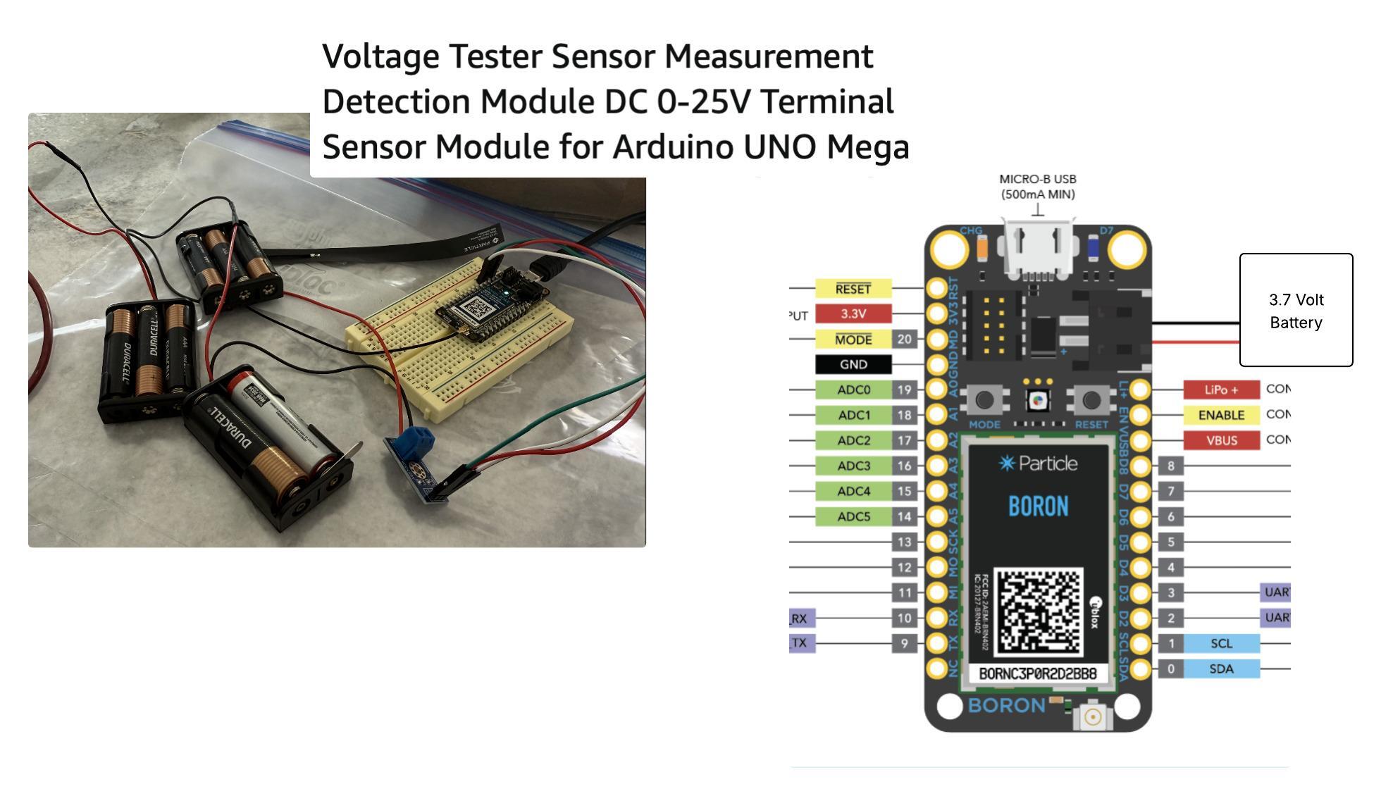
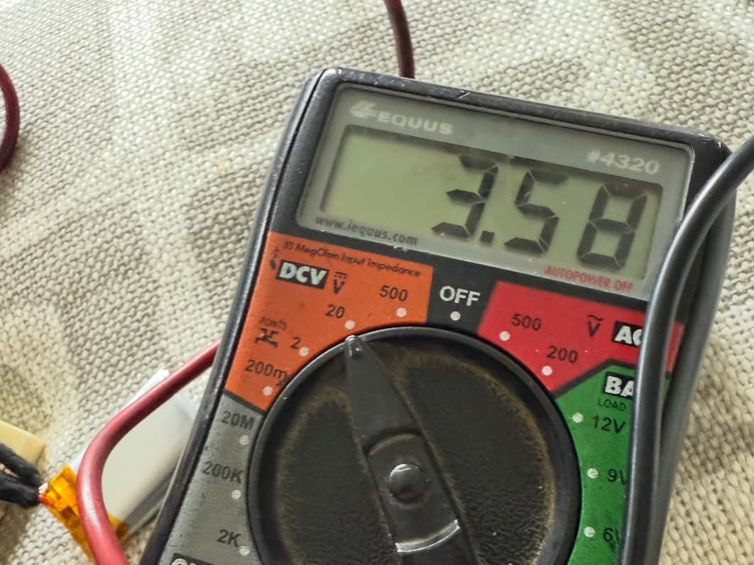
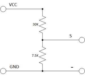
Please see the attached diagram. It is a voltage monitor - it was working great (you see it with some batteries for testing purposes). As soon as I plugged ithe 3.7 volt battery (shown on diagram) it overheated and now solid amber. I tripled checked I had the positive and negative in the right places. I have no idea what I did to mess it up...
Also the reason for the 3.7 volt battery was a backup in case the battery it is connected to and monitoring goes bad.
Hey Brian, can you describe the red/green/white wires you connected to the Boron as well, please?
Yes - that is the voltage sensor detector. It monitors the voltage from a 12 volt auto battery. This device takes the 12 volts and cuts it down by 80% and calculates the voltage based on that. It is this device - Amazon.com: Geekstory Voltage Tester Sensor Measurement Detection Module DC 0-25V Terminal Sensor Module for Arduino UNO Mega Robot Smart Car Geekstory (Pack of 10) : Industrial & Scientific - was working great.
ok, but I must insist ![]()
Can you describe the red/green/white wires you connected to the Boron as well, please?
How did you connect that sensor to the boron?
Thanks
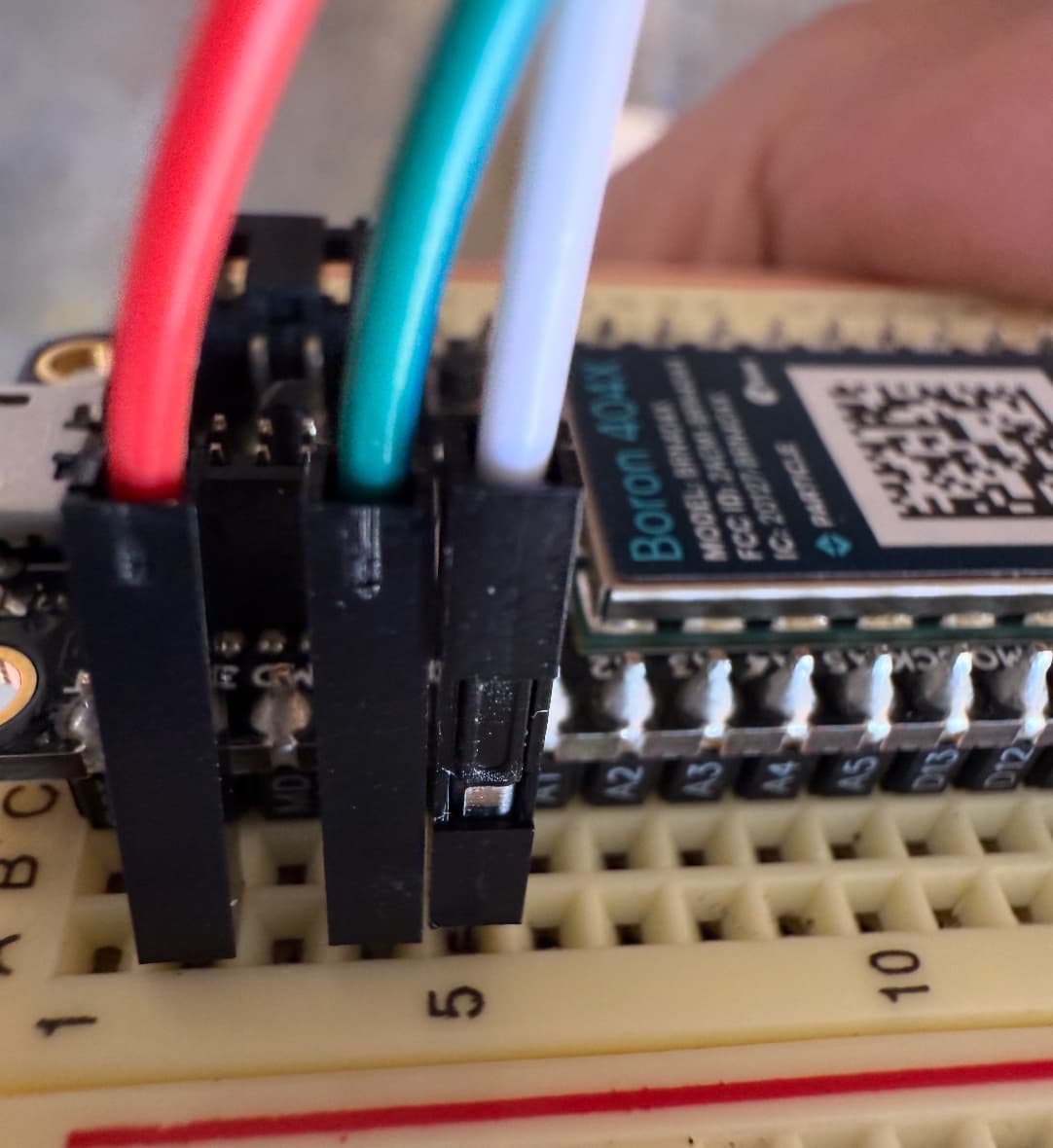
Ha of course and here you go! - I'm a bad explainer, so here was the Grok logic on those three wires - basically a hot, a ground, and a signal - but see below...
- VCC (Typically Red Wire):
- Function: Supplies power to the voltage sensor module. The module itself is passive (uses resistors), but VCC ensures compatibility with the Boron’s logic level (3.3V).
- Connection to Boron: Connect to the Boron’s 3.3V pin.
- Purpose: Provides the reference voltage for the module’s voltage divider output. Since the Boron operates at 3.3V, connecting VCC to the 3.3V pin ensures the signal output (S) is within the Boron’s ADC range (0-3.3V).
- Note: The module’s product description confirms it’s designed for 3.3V systems (input voltage not exceeding 3.3V × 5 = 16.5V). Your 12V battery is within this range, producing ~2.4V at the signal pin (12V / 5 = 2.4V).amazon.com
- GND (Typically Black Wire):
- Function: Provides the common ground reference for the module and Boron, ensuring accurate voltage measurements.
- Connection to Boron: Connect to a GND pin on the Boron.
- Purpose: Completes the circuit for the voltage divider and ensures the Boron and battery share a common ground. This wire also connects to the battery’s negative terminal (via the module’s input terminal) to reference the input voltage.
- Note: The product description specifies the DC input connector’s negative terminal connects to GND, aligning with your schematic’s common ground.amazon.com
- S (Signal, Typically Green or White Wire):
- Function: Outputs the scaled-down voltage from the voltage divider, proportional to the battery voltage.
- Connection to Boron: Connect to the Boron’s A0 pin (as specified in your code: const int VOLTAGE_PIN = A0).
- Purpose: The signal wire carries the divided voltage (e.g., 12V battery → 2.4V at A0) to the Boron’s analog-to-digital converter (ADC) for measurement. Your code reads this voltage, scales it back using DIVIDER_RATIO = 5.0, and calculates the battery voltage (batteryVoltage = measuredVout * DIVIDER_RATIO).
Also, what if you disconnect everything from the boron and restore it with:
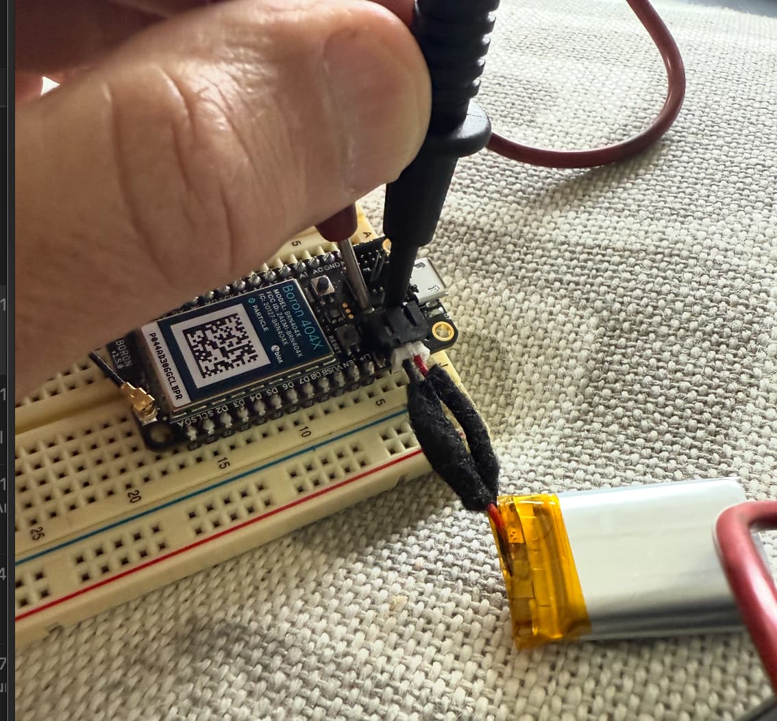
Is the LiPo battery from Particle, Adafruit, or Sparkfun? Or some other vendor (Amazon, eBay, Aliexpress)? The polarity of the JST-PH connector is not standardized. Make sure the polarity is the same as in the battery guide. There is no reverse polarity protection on the LiPo battery connector and it can permanently damage the device if reversed.
Another chance of disaster:
The sensor you bought is a resistor divider - from what I can see.
If by any chance, GND was removed/disconnected temporarily, 12V (or whatever voltage present at the input of the divider) would go straight to the Boron pin, likely damaging it.
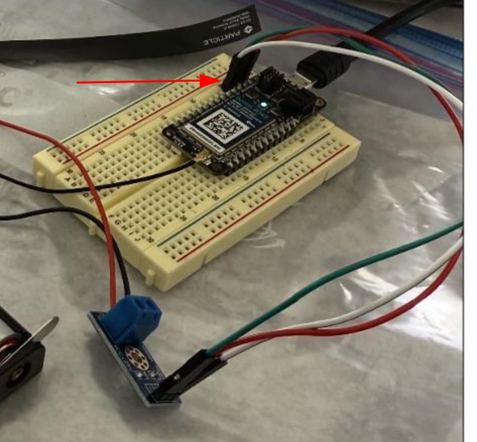
When I plug it into the notebook, it is solid amber. The device can't be seen (or reset). If I plug in the serial cable into a USB power charger,, it flashes amber. But when I plug in the battery (the 3.7 volt) it goes solid. Either way, I can't get it to react in the particle interface. I think I have the positive on the correct side - required changing the battery leads. Also you can see where the battery monitor is plugged in. Thank you!
Just to be clear, there should only be two connections to the sensor board: GND on the Boron to the "-" on the sensor and ADC input on the Boron to the "S" on the sensor. The sensor has NO Vcc (3V3) requirement since it is just a resistor divider.
From what I can see you have 3V3 connected (should not be) to the "+" on the board and the GND and A0 correctly connected.
As @gusgonnet pointed out, accidentally disconnecting the GND would damage the A0 analog input circuit and possibly more. In addition, trying to measure more than 16V would exceed the 3.3v input limit on the A0 input as well.
Got it then thank you so so much. Do you think the attachment of the 3.7 volt battery was just circumstance then? Or did introducing the 3.7 volt backup battery plus the connection to the 3V3 that should not be there make the unit fail? Thank you again.
And adding on here, do you think if the 3v3 connection is open, but I have the USB connection working, it is generally ok to add/drop the 3.7 volt battery?
You can plug or unplug the USB or LiPo battery at any time, in any order.
Also, a resistor divider is not ideal for measuring the voltage of a battery continuously. That particular breakout board has a 30K and a 7.5K resistor, so there's a constant 37.5KΩ between 12V and GND.
By Ohm's law, V=IR, so I=V/R, then:
I=12V/37500Ω = 0.00032A = 0.32mA = 320µA
320µA (microamps) is not huge, so it might not be an issue, but keep in mind that it will constantly be drawing that. For comparison, the Boron 404X uses 130µA in ULP sleep mode.
That is also great advice. Might you have any thoughts on a smarter way to monitor a 12 volt auto battery? I really only would need to have it checked every hour. Is there some sort of more efficient divider that you know of? Thank you !!
perhaps an INA219?
Ok cool. Do you know what the load would be on that? Also, am I right to say that the power terminal on this device that should come from an external 3 to 5 volt (eg usb) source then and not attached to the Boron LTE (meaning the ground and sensor wire go to the boron and the power wire goes directly to power)? I hope I asked that right and thank you!!