Happy Wednesday Particle People.
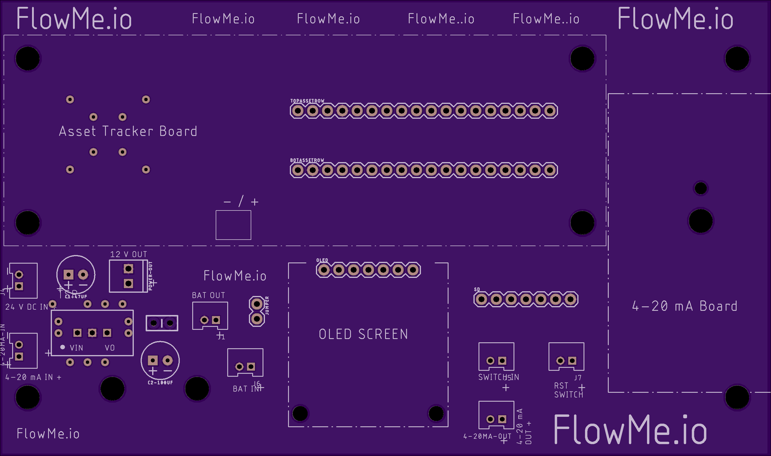
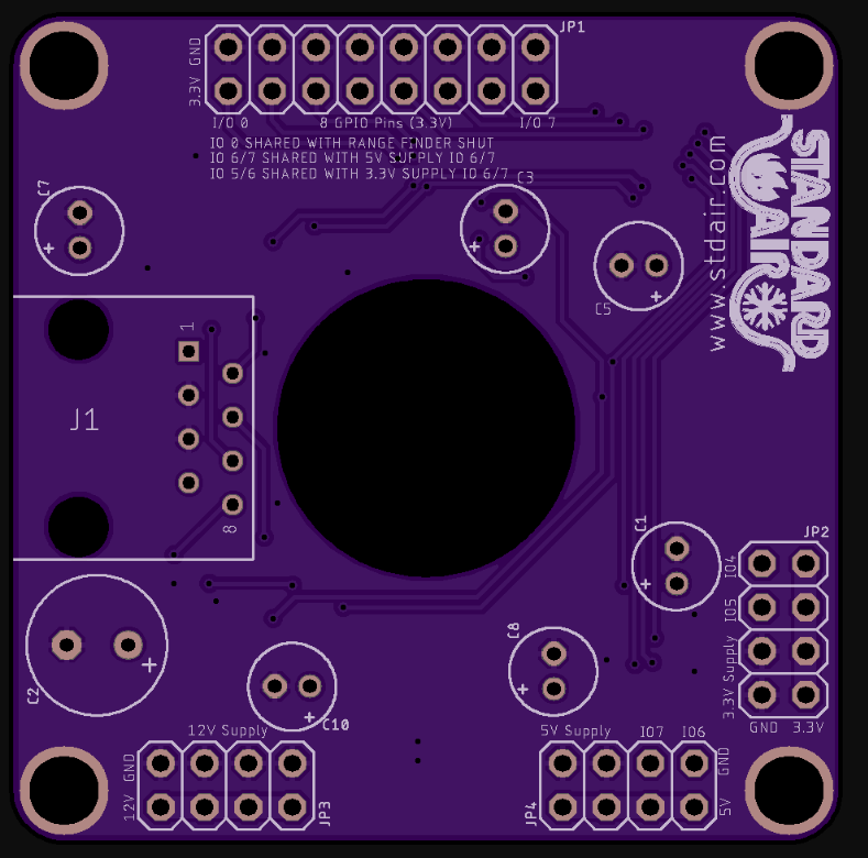
Here is my attempt at using Eagle to create the board to send to OSH Park. I went through about 13 revisions before I settled on this one. I have added a few JST ports to add my inputs, power, batt. I also added two external to JST switch points. One for turning the unit on and off / Battery using a sealed exterior switch, there is a jumper in place that can be used incase the switch fails. The second switch is for a reset button, also on the exterior of the unit. There are some radome Vias placed under heat-generating items, trying to keep a little air flowing around this sealed unit.
Let me know if you have any suggestions or questions. I welcome any input good, bad, or indifferent.
Cheers,
Tom
Eagle View (Note you do not see the ground plane in this image.
@GasGen, you don’t seem to have used the other side of the board for your traces. This will help in keeping your traces short and clean for both power and signal traces. Another trick is to do a ground plane on both sides of the board which helps keep noise down and makes ground connectivity simple. On long power lines you may also want to consider 0.1uF decoupling capacitors as near as possible to the destination pins as possible to reduce noise o the power rails.
How is the asset tracker going to sit/connect to those rows of pads at the top of the board?
@peekay123 Ditto on only using one board plane. If you used the back side for some of the signals, you could have made some of those traces just a quarter of the length. I just received my first board back from OSHPark. Now I have to order a stencil… I didn’t realize how ridiculously small some of the SMD packages are. Happy prototyping!
Thank you @peekay123 and @ninjatill for taking the time to view and comment. So I thought I was being clever by putting all the traces on the bottom of the board, lol. It does not show in the picture but I do have a ground plane on the top of the board. I will add one to the bottom as well.
Would you suggest I separate the power to bottom and data to top, or just mix and match to achieve the shortest lines possible? As a noob I don’t know if it is more important to have them on different sides or as short as possible. I would asssume shorter is better but I bet there is a sweet spot for both.
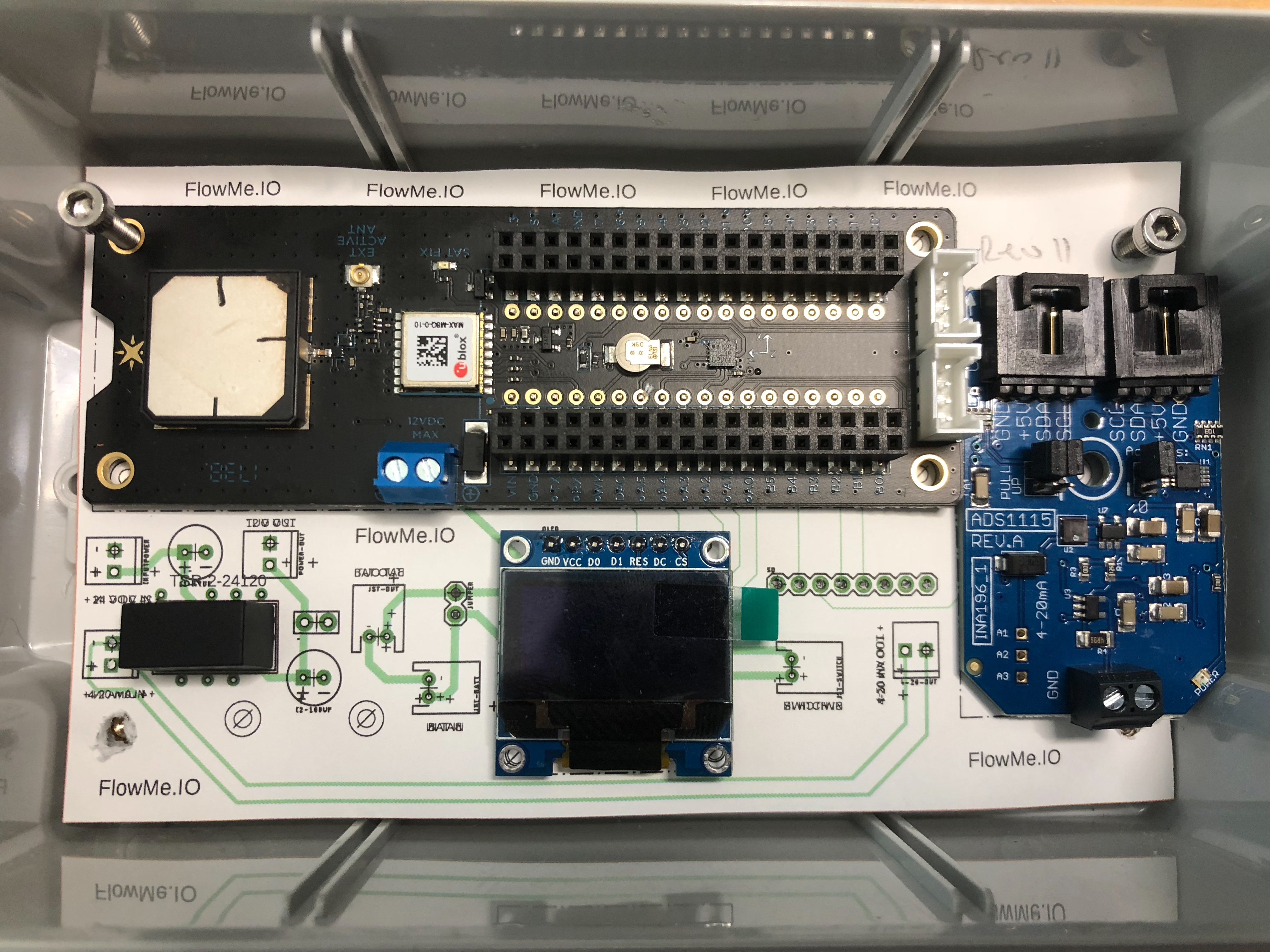
@peekay123 in answer to your question about how to attach the asset tracker. My plan was to solder two 18 row female headers to the new board, and two male pin rows to the asset tracker inner holes. The picture below of my sample kind of shows what I had planned. Not the best photo but I hope it gives you and idea if what I had in mind. Ignore some of the layout as this was an older revision print to check the line up of parts. You can see the pins the asset tracker inner holes are sitting on.
Good morning Particle.
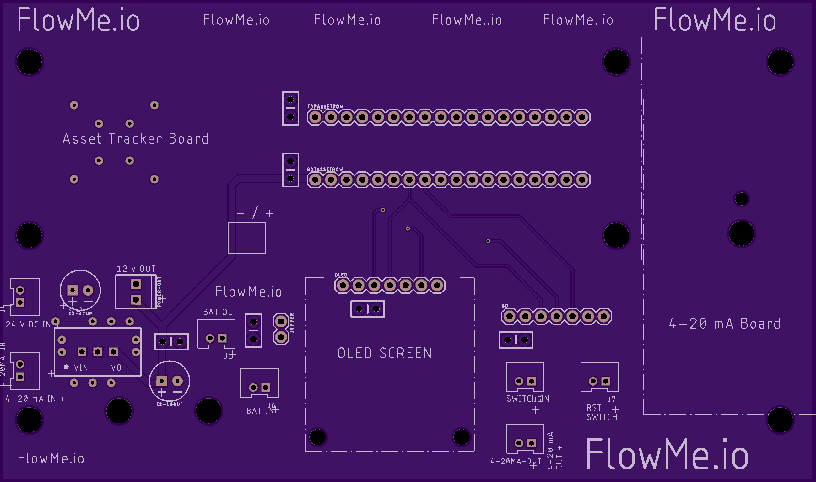
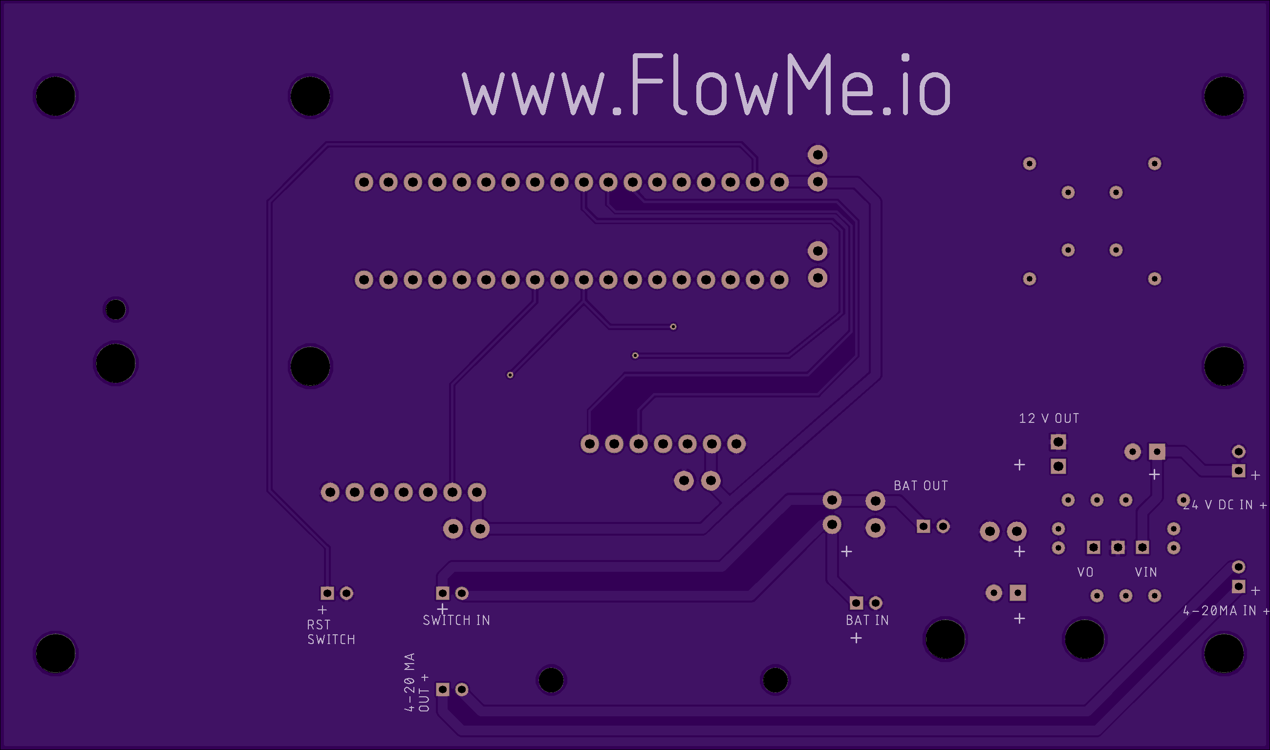
Here is this mornings update taking @peekay123 and @ninjatill suggestions. I added the second ground plane to the bottom of the board. Changed some of the routings to utilize both sides of the board. I have also added the decoupling caps… maybe went a little overboard and added ones to the SD card and OLED screen. I hope I can use just regular ceramic ones and bend them slightly as there is no way my hands are steady enough for the surface mount.
Looks cleaner. And you probably won’t have as much noise on some of those signal lines. I remember back to my EE101 class where we had to etch our own PCBs. We could only do single-sided boards so the professor challenged us to make our traces with the least number of vias/jumpers. But fast forward almost 20 years and we have resources like OSHpark. When using a fab house, I figure that they are charging me for both sides whether I use them or not. So I still keep that “minimal number of vias” mentality but I wholeheartedly use both sides of the board to maximum effect. Here’s my first fab house board. They look big in the pic but are only 48mm to a side. Despite numerous revisions prior to ordering, I found a mistake as soon as I received them. Luckily it’s only on the silkscreen text. Haven’t tested it electrically yet.
@GasGen, for your first board, it’s looking better! You may want to consider routing your RESET line on the top layer to get a less meandering line. Have you tried viewing the board in 3D to look at possible “tight spots” around the connectors, etc.?
Thank you sir. I have not been able to figure out how to export it into a viewable 3d file. Still trying to figure that part of Eagle out. Lots to learn.
The new boards arrived yesterday. Wired everything up and believe it or not it actually works.
These larger boards are more for internal use as clients won’t need the asset tracker. I need it because the loaner units tend to wander off. Soldering pins to the inside rows on the asset tracker was a little sketchy but I managed not to melt anything.
One thing to note is how difficult it is to make the JST plugs. Those crimp on inserts are so dang small, definitely not as easy as a Molex. I may change the inputs and such to something a little easier to make.
The 2mm screws did not arrive yet for the OLED but as soon as they do it will it get secured to the board… but I am impatient and wanted to see everything else mounted while I wait.
Input, feedback, criticism, ideas, are all welcome. Fire away.
Thank you Ryan,
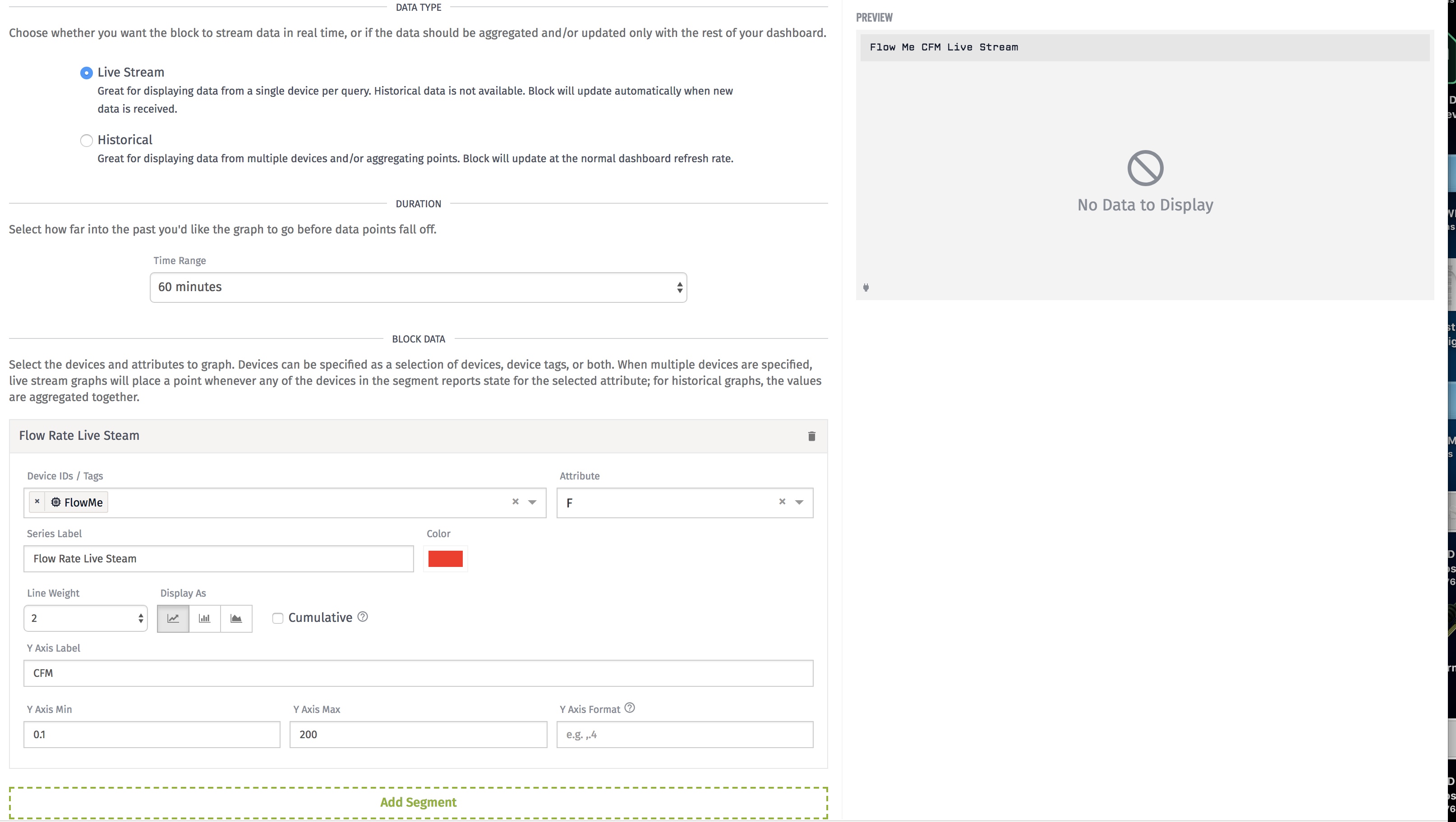
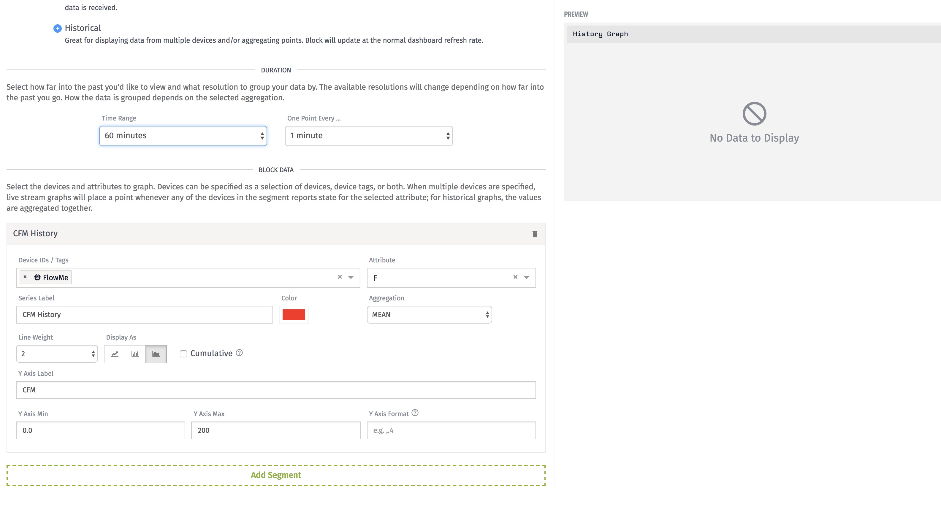
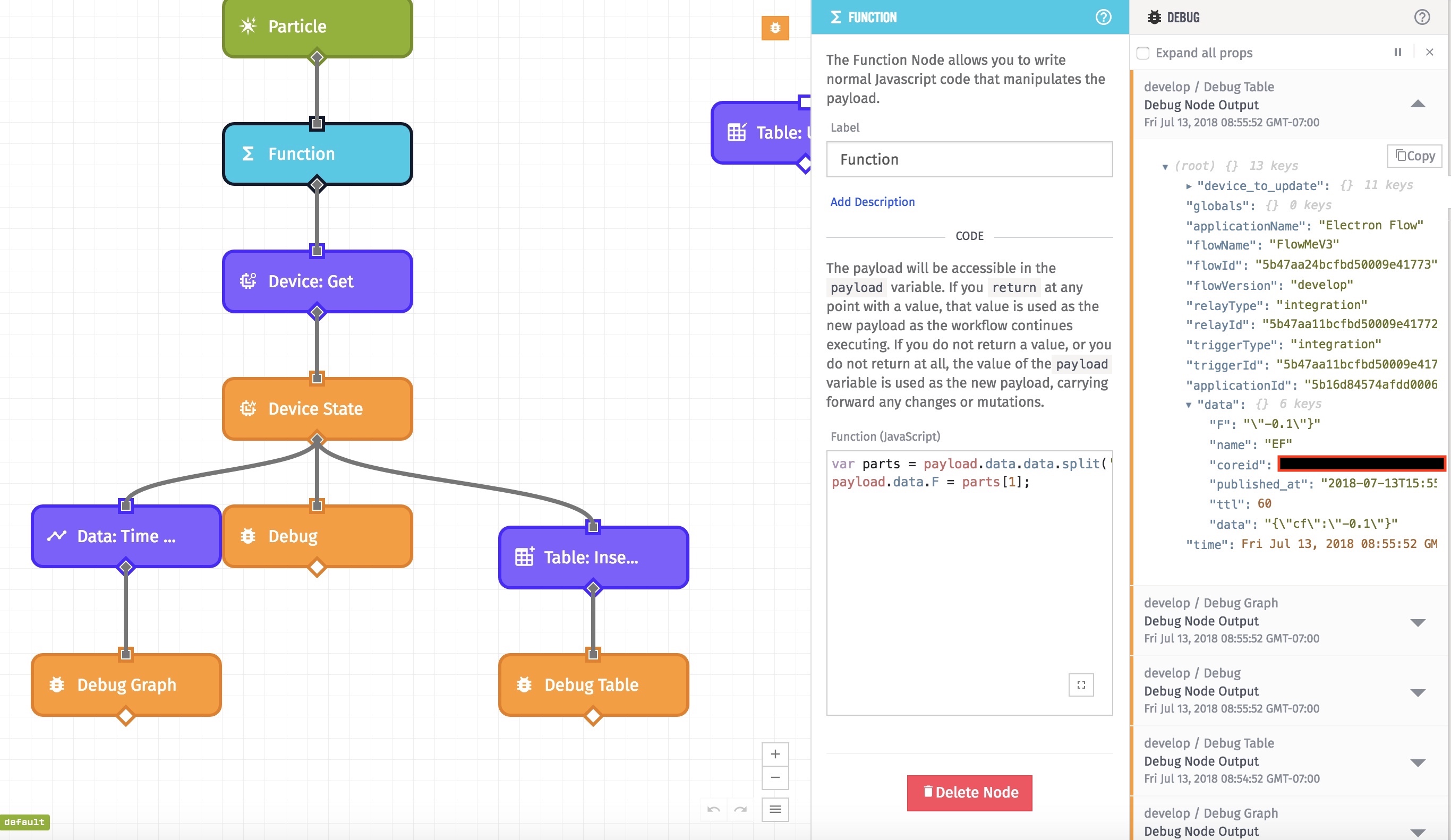
Now working on a smaller version along with trying to tackle Losant. I am making some progress but stuck on a few little things trying to graph the data… story of my life with the new IOT project I have created for myself. lol.
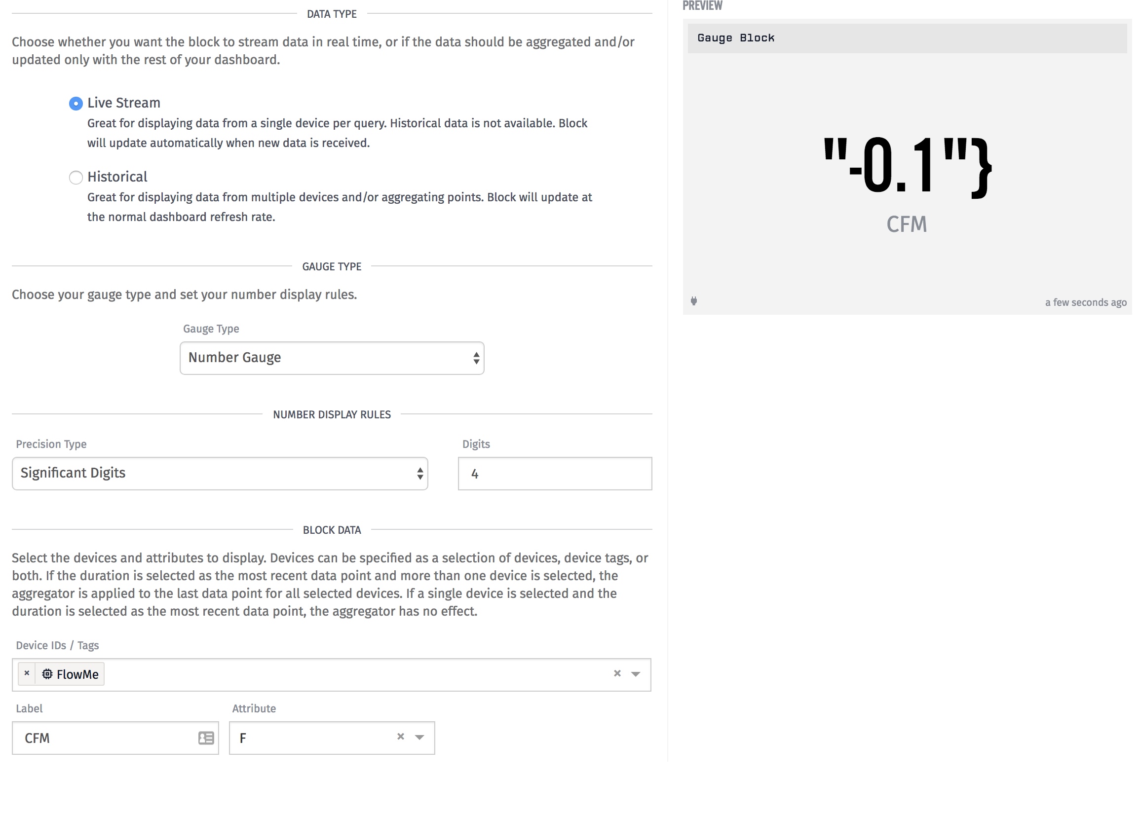
Sure did. Was able to get the Dial gauge to show the flow but can’t seem to get the time graph to work. Gotta read more examples and keep trying. Was able to make a table so I have that going for me. lol.
Show a screenshot of your gauge settings so I can compare because if the data is showing up for that same variable as expected then there is no reason it shouldn’t show up in the graph also.