@BDub every suggestion you made is spot on and I will make these changes. I used the SD Card and not the micro as I haven’t found the microSD.lib yet. I might just create it from a datasheet. The female headers that’s elevation I did not consider; duh bobby.
Is this long & short layout better than say a square type layout ? Could make it square and put SD Car to side of Core ?
enter preformatted text here
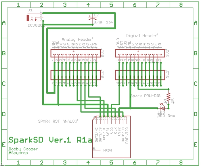
What is the VDDA used for` ?
Found my erorr VDDA lable should be VIN
What creating pads for both SD & Micro and board could be built for either but, not both. micro SD cards are more expensive when you get up past 8GB (I’m just cheap).
Actually RAW should be labeled VIN and VDDA should be labeled 3V3*
If you are using Eagle, grab Sparkfun's library.. there is bound to be a micro SD card holder in there. If you need a part number for one, I know the one they use... got it somewhere here.
Long or Square will work either way... but you are putting this into a project box, I'm sure Long is a little easier to find a slim looking case for. If you made it the same size as the spark core, you could use stacking headers and plug it into a breadboard without giving up any space around it for connections/components... and it would be easier to produce. You might even be able to get your finger in under the micro USB connector to eject the card, without removing the core from the breadboard... maybe... testing... yep!
@BDub I do like very small and less parts, simpler & cheaper but, adding the DC jack & Cap allows powering the Spark SD with 4 AA batteries or 6v adapter while allowing the core to reside on a bread board during prototype testing. With the bigger PCB I can pad it for both micro SD and SD Card and option of using either type card.
<Post Update: Will change RAW to VIN; Will Change VIN (below image) to 3V3 - Thanks for help - I need it >
Will the micro SD slot fit between the .700" female header spacing ? If it will, I will make both PCB designs and people can choose their digital storage option.
Revised the Spark SD with all of your suggestions and a couple more.
Rotated Core so Antenna is away from SD Card [Check]
Moved LED From D0 to D6 [Check]
Proper lable for Pos Tip to Pin=VIN [Check]
.0629" Mounting holes = [Quad Check]
Also Revised:
Increased Trace size for + / - Rails to .040". All other traces are .024"
Marked Orientation for Core Placement.
TODO: Add sd Micro Slot pads as well on the larger PCB.
Still Need Feedback prior to Proto Cost Estimate. Anything else that would be useful on this version ?
Above Revisions should be correct. VIN, 3V3 Properly labled. + Pos Tip going to VIN.
I would really appreciate feed back on this, need any correction or additions to make better;.
Once this is sent to proto-fab, I will work on a much smaller version with micro SD, No DC Jack; No Capacitor, will keep LED/Resistor to Pin D6.
Updated: ONE LAST THING: The External headers are two fold and most will know this: 1) To allow connections to all pins for prototyping and 2) So it can be stacked with other cards such as a relay board; or a battery board and any board that is either on Spark Core Pin Header Layout or what I have designed which is .400" wider than the Core header width of .700"
I don't know how much feedback you want, but I really feel like getting into your layout and fixing up a bunch of connections. Make use of vias and try not to snake tracks between pins if you don't have to. Also route them away from nodes they shouldn't short to rather than super close past them. Rule of thumb is usually if you have space between two nodes that are not the same as the node you are routing, you route it equidistant between them. Unless it's preferable to route it closer to one than the other (and there are many reasons for this). Use 45 degree miters on corners. Don't exit pads out the side at angles if you can, exit straight out, then make a turn.
Are you using Eagle? Why are your traces so thick in the schematic view Just wondering if you are routing with buses, or intentionally making your "wires" thicker for some reason.
Can we do both this layout size and a very small (closest to Core size) layout ? Of course, only the microSD slot would be on the small one.
Heck yea you can pick this up and I know you can do a better job than I; that would be great. I don’t need my name on it, I only did that if someone had questions they would know who done it. (Done it badly too
Without your expertise I would still be trying to build an HTML/JAVA (Or PHP) control for my project let alone trying to layout correctly a SparkSD Shield.
I will send you some additional thoughts, suggestions and link to eagle cad files.
(Moved from another topic as it relates to this SparkSD Card design)
Its okay if you start from scratch, I am the novice here - just trying to help --> push–> push things along not that it needs to be pushed at all.
Yes, I personally believe there needs to be a smaller standard than Arduino shield layout because they don’t need to be full out all inclusive commercial products… A relay board can be designed to work with off the shelf purchased relays of different voltages & option to pull it down with NPN or power it with PNP transistors and iosolation. Its a can of worms I would like to see opened up to make it easier for people to build what they want and the shields built with some tweaking ability. How does one customize an Arduino controlled relay board to work with their project; they can’t. You either build your product to the relay board configuration or you have to build a complete relay board too. Do you see what I see ? Most projects are 12v, 9v, or 5v. These voltages are all possible on a very small footprint with a LM317T regulator and appropriate resistors layout with minimal heat generation… User moves jumpers to select voltage level for his relay / project just like the old days with PC hardware cards but, this is just me. This particular SparkSD shield is not part of what I call adjustable shields so as to “let hobbyist finish the rest” approach.
I want to get along with you and the others; the experts of this community. However, when I become an expert “of something” - Look Out as I am going to take over the world (with my Spark Core of course) (LOL)
My benefit and off set for the time I spend helping others is offset 20x by what I learn and just maybe I am able to save someone time as well. Okay, my PCB - “I should not quit my day job”, sorry too late
I am also not in it for the money on these things. I only have a Patend Pending on my own products to keep others from stopping them. When you are wanting to sell a device that can stop NSA spying in a home or business; there will be some blowback against what I am trying to accomplish.
Always know that I will need to be told its not working Bobby, this is how you do and I will never be offended; I will be happy to know someone cares enough to help not only me but, the community as a whole and that is very important to me.
Always willing to recognize those who deserve to have credit given as without them my products won’t ever make it to market.
I just want to this entire thread. Gives me warm, fuzzy, goose pimples and gets me a bit choked up. Just exactly what we hope enables in the world. I love you all!
NaAl, it’s not about digital or analog. The microSD uses the hardware SPI bus which uses A2 to A5 and no other pins. However, I believe BDub and I can modify the library to also use software SPI. It will be slower in terms of transfer speed but it should work and allow you to use other pins. Stay tuned!
What @peekay123 is saying is totally doable, and I did it with my LiquidCrystalSPI library. It’s actually just as fast as the hardware SPI in that implementation, and should be for this one as well. Just need time to make an overloaded constructor and add the method.
If you just need one extra A/D, right now you can change the library to move the A2 pin to a digital pin like this: chipSelectPin_ = D2; SPI.begin(D2);
Can anyone paste a code how I get mem card size and left space to Serial and also write those values into SD card file? I’ve tried to use different example files but after getting SD card total size then writeing failed and Spark flashes red led.
Thanks!
markopraakli, can you please explain a little more what you are trying to do? Could you post the code you are having problems with. Are you trying to write the SD card size and remaining space to an SD file? If so, in which format - text, binary?
// Now we will try to open the 'volume'/'partition' - it should be FAT16 or FAT32
if(volume.init(card))
{
    // print the type and size of the first FAT-type volume
    uint32_t volumesize;
    Serial.print("[SD] Opened (FAT-");
    Serial.print(volume.fatType(), DEC);
    Serial.println(")");
    volumesize = volume.blocksPerCluster(); // clusters are collections of blocks
    volumesize *= volume.clusterCount(); // we'll have a lot of clusters
    volumesize *= 512; // SD card blocks are always 512 bytes
    volumesize /= 1024;
// open the file. note that only one file can be open at a time,
// so you have to close this one before opening another.
myFile = SD.open("test.txt", FILE_WRITE);
// if the file opened okay, write to it:
if (myFile) {
Serial.print("[SD] Writing to test.txt...");
myFile.println("testing 1, 2, 3.");
// close the file:
myFile.close();
Serial.println("[SD] done.");
} else {
// if the file didn't open, print an error:
Serial.println("[SD] error opening test.txt");
}
 that’s elevation I did not consider; duh bobby.


 Core on GitHub that one might find useful while designing things around the Core!
 this entire thread. Gives me warm, fuzzy, goose pimples and gets me a bit choked up. Just exactly what we hope
  enables in the world. I love you all!