Hi,
I’m brand new to the Photon but have a little bit of experience with Arduino, and I was wondering if anyone could help me hook up the above shield to the Photon. I’m trying to use the ADAFRUIT_ILI9341 library, but it doesn’t work in the online IDE, I get a million errors about BRR not existing. I’ve seen that there are a few forks of this library and I think I’ve got everything compiling correctly in the offline IDE, but I’m still not sure of the wiring that I’ll need from the Photon to the shield. I’ve tried what is suggested in the comments but to no avail. Has anyone ever hooked up these things before? If so can you share some knowledge?
Thanks in advance
Ross
This lib was originally ported for the Spark Core and hasn’t been updated yet for the Photon.
But if you are prepared to tweak the library yourself it’s not too difficult and we can provide some pointers.
The main thing there is that you should replace any occurences of pinLO()/pinHI() with their hardware independent counterparts pinResetFast()/pinSetFast().
According wiring, when usint it via SPI look at this
https://docs.particle.io/reference/firmware/photon/#spi
And for CS & CD you might need to look into the code, since these pins can be assigned by you.
1 Like
Hey @ScruffR
Thanks for your reply, I’m attempting to use it as a SPI.
I’m more than happy to tweak the library, is there anything else that I should look out for?
You might also get some warnings/errors about pgm_... since these are not required on this platform.
This might also be helpful
Preprocessor #ifdef to Detect Platform Type (Core/Photon) at Compile Time
But there are lots of possible issues that might (or might not) come up, so it’ll be best to address them when you see them rather than getting worried about them before hand 
Yeah so I’ve checked the SPI reference and using this as a reference I have connected what would be the pins on the Arduino as follows:
D13 -> A3
D12 -> A4
D11 -> A5
D10 -> A2
D9 -> A1
And Gnd and 3V3 to the relevant pins.
Is there anything that I am obviously missing?
I am instantiating the TFT lib like so:
Adafruit_ILI9341 tft = Adafruit_ILI9341(A2, A1, A0);
The backlight is working but nothing is drawn.
Rest of the program:
#include "Adafruit_mfGFX.h"
#include "Adafruit_ILI9341.h"

Adafruit_ILI9341 tft = Adafruit_ILI9341(A2, A1, A0);

void setup() {
    tft.begin();
}

void loop() {
    tft.setRotation(1);
    tft.setCursor(50, 50);
    tft.setTextColor(ILI9341_BLACK); tft.setTextSize(8);
    tft.print("Hello world.");
}
Try powering the board off Vin pin. I’d think it needs 5V supply and there is a 3V3 regulator on the board, so 3V3 supply might be just a bit low.
I’ve not looked into the Arduino shield pin mappings, but the onboard silk seems a bit confusing - which pin is where?
But you wiring table looks good.
So this http://linksprite.com/wiki/index.php5?title=Touch_LCD_Shield#Schematics and this: https://s3.amazonaws.com/linksprite/Shields/touch_LCD_shield/TFT+Touch.pdf were linked from in the booklet that came with the screen. So perhaps in that case the pins are slightly different from above.
Not really familiar with SPI, whats the “D10: SPI chip select” vs “D5: TFT_CS, TFT chip select input pin”?
Thanks for your help btw!
The CS pin on the board can be connected to any free digital pin.
That’s the reason why you’d have to specify the chosen pin in the library constructor
Adafruit_ILI9341(uint8_t CS, uint8_t RS, uint8_t RST);
e.g. if you have multiple SPI devices connected (TFT + SD + cap. touch screen), they all share CLK, MOSI and MISO, but each of them has to have its own CS where these have to be active mutually exclusive.
Hence the lib must know which pin to activate before communication and deactivate when done.
Sometimes it helps to check the wiring to upload a pic that shows the Photon and the connected device with well distinguishably colored jumper wires
Lol yeah good point, couple of pics here, but its not very good, pretty hard to distinguish the pins 
Now I’ve hooked up the TFT CS pin to D0, the TFT DC pin to D1 and Reset to D2, and called the constructor accordingly. Still nothing, just a white screen.
@rossdeane, quick review of pins:
Photon        Display (UNO equivalent pin)
  A1           TFT_D/C (D6)
  A2 (SS)      TFT_CS (D10)
  A3 (CLK)     SPI CLK (D13)
  A4 (MISO)    SPI MISO (D12)
  A5 (MOSI)    SPI MOSI (D13)
According to the docs, there is no RST pin so the pin you specify will not do anything. One concern is the SPI DIV2 clock used in the code which was setup for a Core and which may be too fast on the Photon. I’ll have to update my (non IDE) library in my repo with all the goodies that are now available on the Core and Photon!

I guess the copy-paste ![]() devil has hit here
devil has hit here ![]()
Actually @rossdeane, now @peekay123 mentioned the DIV2, I recall someone else having a similar issue and going for DIV4 settled his problem.
You’ve got the lib editable already, just give it a try
void Adafruit_ILI9341::begin(void) {
	...
	SPI.begin();
	//SPI.setClockDivider(SPI_CLOCK_DIV2);	//Full speed @19MHz on Core
	SPI.setClockDivider(SPI_CLOCK_DIV4);	//Full speed @15MHz on Photon
	SPI.setBitOrder(MSBFIRST);
	SPI.setDataMode(SPI_MODE0);
	...
}
1 Like
I am using the DIV2 (as in unaltered) from ILI9341 library with an Adafruit Ili9340C (tft but not touch) and it has been behaving just fine with my Photon.
@svartbjorn, that’s good to hear 
So it rules out one suspission. Have you got any other suggestions for @rossdeane?
Since I’ve not got any ILI display, I can only stab in the dark.
At the moment I’m still tempted to go for the wiring and the pics don’t really allow to judge where the jumpers go on the display.
Ross, could you maybe shoot a pic of the bottom/header side of the display rather than showing the black screen Maybe you could use male-female or female-female jumper wires and directly plug them into the display to make it easier to see.
Or at least confirm, that the breadboard column 1 is actually connected to the first pin on the display headers.
@ScruffR, I have an ILI9341 display but not that exact one. It is working with a Core but I will test with a the new 0.4.5 firmware tonight.
1 Like
I’m trying to remember what I did to fix things because I went through this exact problem when I hooked up my Adafruit ILI9340C the first time. White screen, nothing else.
My best recollection is that I was not hooking up the RST wire (at one point I was even hooking up RST on the display to RST on the Photon (this did not go well  ). Once I did that all was well.
But I think it was established that there is no RST for this display. I’ll just throw out this which is my comments in my code for how I have my display hooked up, and the corresponding call to the library.
A2 : SS(Slave Select) for DISPLAY CS - Chip select (aka slave select)
A3 : SCK(Serial Clock)
A4 : MISO(Master In Slave Out)
A5 : MOSI(Master Out Slave In)
TX : BL Backlight (allows dimming) with PWM
D4 : dc - D/C or A0 on the screen (Command/Data switch)
D5 : rst - Reset pin for display
D6 : SD_CS CS for the SD Card
Adafruit_ILI9341 tft = Adafruit_ILI9341(A2, D4, D5 );
I believe A3,A4,A5 are mandatory mappings to use hardware SPI. I had need of as many Analog pins as I could so I mapped anything that could be Digital to a digital pin.
One thing to be very sure of is that you are using the Display’s CS pin for SS (A2) in my case. I think you have 3 CS flavors for the touch screen, so be sure it’s the right one.
1 Like
Just to suggest a couple of things, since the screen starts white, you can’t be sure if anything is happening. I suggest a line like:
tft.fillScreen(BG_COLOR); //Where BG_COLOR is something you define that is not black or white.
I also suggest you do this in setup after tft.begin();
The other thing is to explicitly set a font before you print just to be sure things are OK in the font definitions. I really doubt this is the problem, but every clue helps.
Just to make sure the SD-Slot doesn’t interfere, you might also want to explicitly deactivate it via TF_CS (odd name for an SD slot ;-)) at pin D4 on the board by adding this to your setup()
#define SD_CS D0  // accroding to your white wire in the pic above

void setup()
{
  ...
  pinMode(SD_CS, INPUT_PULLUP);
  // or if you intend to use the SD slot some time
  pinMode(SD_CS, OUTPUT);
  digitalWrite(SD_CS, HIGH);  // since it's an active LOW logic
  ...
}
Or just remove any card that might be in the slot 
According to the LinkSprite schematics there seems to be a not-marked RESET pin on the board you could also try pulling this pin high.
And could you also provide a pic how you’ve powered the shield?
@rossdeane, I’ve just realized that there is also a v2 of that board which has more pins

(source of pic http://www.adafruit.com/products/1651)
This is the pinout of an Arduino shield (seen from the top - needs to be flipped to fit the above pic)
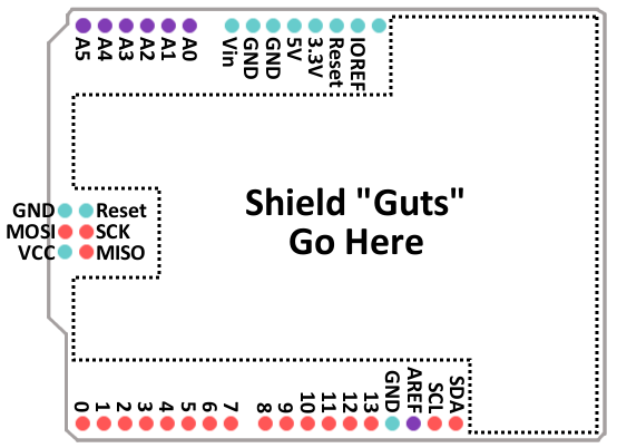
(source of pic https://cdn.sparkfun.com)
Could it be that you’ve got this one?
If so, your wiring would be two pins off, which would explain a lot 
1 Like
Hey guys, I have read this discussion and I find it really interesting. But, because I’m totally new at this. I still don’t know what pins are wired to which and what wire. Can someone please guide me step to step on the wire and placement on the board? Thank you 