I am powering it with a 12V power supply along with a N-Channel MOSFET to control it with a pin from my photon. I have a kickback diode between the power and ground of the solenoid as recommended. My problem is that when the photon pin is thrown HIGH the valve opens up but stays open even if the pin is thrown LOW or just disconnected completely. The valve will only close once I disconnect the power supply. What do I do to get the valve to close when the pin is thrown LOW.
Thanks in advance for any help.
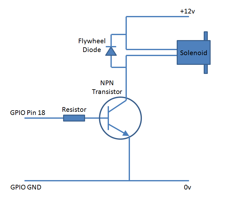
Also the image shown below is pretty much how I have my system wired up.
@nbmoretto, are you using an N-MOSFET or a bipolar transistor? If you are using an FET, you need a 10K GATE resistor to ground to hold the gate OFF. Without the resistor, the gate will charge and the large source-to-drain current will keep the FET ON. You don’t need the current limiting series resistor IMO though. Which FET are you using?
EDIT: Should the ground off the photon and 12v power supply be connected together? If I do add the 10K resistor do I connect it to the ground of the power supply or the photon?
@peekay123 I just measured the voltage and it seems as though I may have a bad MOSFET. I am getting 2.5V on the GATE even when no pin from the photon is connected.
Did you look at the FET data sheet for how to hook it up? The pins are from left to right with the heat-sink to the back: gate, drain, source, so gate gets the resistor to the Photon, drain goes to the solenoid/diode and source goes to the common ground connected to both the Photon and the 12V power supply.
Another good thing to try is to remove the end of the resistor connect to the Photon pin and make sure you can trigger the solenoid by touching it to +3.3V on the photon.
@bko thank you for your response. It seems as though I may need to get a new MOSFET before I give this another go. Quick question, the resistor from the gate to the photon, what resistance should that be? Also do I need a 10k resistor from the GATE to the ground in addition to that resistor?
The reason for why I say I need a new MOSFET is because the solenoid stays open even when nothing is triggering the MOSFET. I will get a new one tomorrow hopefully and try redoing this.
Almost no current enters the gate–the spec says 100nA. Since the max gate threshold for turn on is 2.85V and you are driving it with 3.3V, you could use a very large resistor up to several megohm, but a nice safe value is 10k ohm. If you do use a series resistor on the gate, the gate to ground resistor needs to be much larger or you can pull the Photon pin down on the “other” side of the series resistor.
As @peekay123 said though, the series resistor is not really required but the resistor from gate to ground will help with potential problems.
Have you tried touching the gate to the +12V supply gnd and +12V terminals to see if the solenoid will trip? The FETs are very robust and hard to kill so I would try to be sure.
If you don’t use a flyback diode, you’ll short the MOSFET so it does what you’re describing. ALWAYS use that diode, which will keep you safe, or you may damage more than just the FET.
This particular MOSFET has a built-in reverse protection diode that is rated for 62A continuous and 250A pulsed, so I think it unlikely that the solenoid could do any damage with inductive kickback. Still the diode is good practice so your advice is good.
The parasitic diode doesn’t conduct in this configuration, so it doesn’t help. When the inductive circuit opens, the amps decrease as the volts increase as the EM field collapses. Usually to around 400V before it finds a way to discharge. So you have -400V on the + side of the coil, and +400V on the - side. The freewheel diode conducts because the positive charge is now on the anode side, as well as negative on the cathode. The cathode of the parasitic diode is connected to the coil end which now has a positive charge so it doesn’t conduct. And to complete the circuit, the power supply is on the other end of the coil. That makes the tiny gap in the MOSFET the easiest way to discharge.
The parasitic (or body) diode operates in the opposite direction of normal current flow while the inductive load is charged in the normal direction. Even if it did, it would be sending the high voltage spike through the supply or anything in the way to complete the circuit. The freewheel diode is operating only in the direction of the charged load, completing the circuit only when discharging the load. The parasitic diode is only good for reverse current across the MOSFET from source to drain, while this is forward current at a voltage level well above spec. It’s the volts, not the amps that arc.
We are in perfect agreement on the need for the diode. All I am trying to say is that I have used these devices and they are very robust and hard to kill. Even accidentally switching 300V due to another component failure in a large power supply did not kill one device, for instance.
Oh yes, it’s a great MOSFET, but the kick from a relay coil is brutal. I make NOS controllers that drive 12A solenoids, and they’re nothing compared to a fine gauge wire relay. Induction gets tricky when it seems like little is going on, until you realize you’re a step closer to a Tesla coil. No MOSFET is safe from flyback, and that freewheel diode protects it every time it switches off.
Hi, Not a good circuit. So lets clarify a few things first, one is it an N-channel mosfet or a bipolar transistor? The symbol used is for a bipolar transistor which is why I ask. If it is an enhancement mode n-channel MOSFET then the diode is not needed since the parasitic diode in the MOSFET will provide the necessary protection, but lets get to that.
The diode in the case of a bipolar transistor is to prevent the collector/emitter pair from becoming reverse biased when the inductor in the solenoid generates a negative voltage potential when the transistor switches off. Based on how quickly you turn it off (and most transistors can turn off in a few tens of nanoseconds, the negative voltage that appears at the collector (or source for a MOSFET) will be -Ldi/dt where L is the inductance of the solenoid’s coil.
Without a diode between emitter and collector, (or drain and source) the collector (source) will “see” a voltage that is negative with respect to ground. That that can exceed the breakdown voltage of the emitter diode resulting in destruction of the transistor. In MOSFETs there is a parasitic diode formed between the drain and the source which will conduct that current protecting the transistor.
Generally, if you’re using an N-Channel MOSFET for this sort of circuit it is useful to have a pull down resistor on the gate. Since MOSFETs are voltage controlled devices rather than current controlled, a floating gate can accumulate charge and slowly switch on, activating your solenoid unexpectedly. But put a 10 - 50K resistor to ground from the Gate and it will keep the gate from accumulating charge and thus from turning on. For a single connection to a MOSFET you don’t actually need a resistor between the Particle board and the Gate. The current limit on the Particles I/O pins will keep it from drawing too much current when the gate is charging.
 No MOSFET is safe from flyback, and that freewheel diode protects it every time it switches off.