I’m very noob to electronics/hardware, have just found Electron and Asset Tracker. Amazing, and thank you! I’ve successfully built the asset tracking system, and have it sending data to my API.
I now want to add another sensor or ten to the Asset Tracker shield, but I’m struggling to understand how it works. A couple of questions for you…
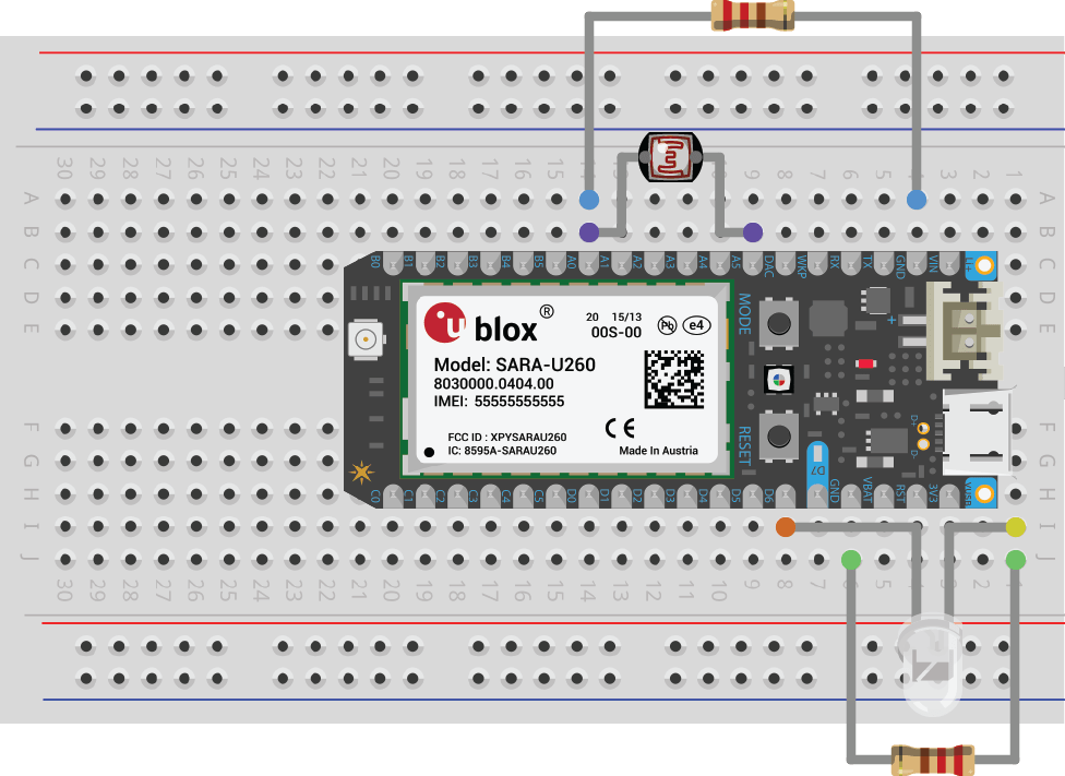
I want to add the photoresistor, to have similar functionality as it has on a plain vanilla Electron (image below from Electron docs). I’m assuming I need to use my breadboard, but beyond that I can’t get different configurations to work. Does anyone have a photo of an Asset Tracker shield with another sensor connected to it? It would help guide me.
Is there is a limit to numbers of sensors that I can include (beyond number of pins) - due to power/charge/processing power of the Electron etc? I imagine connecting quite a few sensors (weather, gas, light, noise etc.), but not sure if there are other technical limitations I need to be aware of?
Yes there is a limit, but that's very much depending on your sensors and how your use them.
The maximum toral current all GPIOs can source/sink at any given time is stated with 120mA (25mA max. per pin), but you don't need to have all sensors powered all the time.
So you won't get a definitive number as answer to that question.
BTW, the pin count doesn't limit your sensor cound per se either. You've got several busses at hand and can do multiplexing too.
The Asset Tracker shield sports a proto area where you can solder any component you like. Add jumpers to the desired GPIO pin holes and you'll be good.
By the way, there are two ways to conveniently use the AssetTracker with a breadboard for prototyping.
Since the AssetTracker has a double row of female header pins on top and the Electron fits in the inner set of female holes, you can simply use jumper wires to connect the outer row to your breadboard. Simple and reversible.
However, if you remove the Electron you’ll also notice a set of through holes just inside the female headers on the AssetTracker. These are designed so you can solder male header pins on the underside of the AssetTracker so you can plug it directly into a breadboard. This makes sense for a more permanent prototype, or if you have a lot of connections.
The picture shows an AssetTracker with male header pins on the bottom, only for the pins that are in common with the Photon, not the B and C pins.
Thanks both @rickkas7@ScruffR. Both those replies help point me in the correct direction regarding adding sensors, and help me understand constraints re load. Cheers
Thank you for posting this answer. I am finalizing my PCB prototype design in Eagle and did a quick search to confirm I can use the holes on the asset tracker and solder pins to them. As usual I found the answer here. Appreciate you all keeping us well informed. Now we will see if I can keep my hands steady enough not to melt anything when I am doing it.